UDM-RX02N Wiring and Connections
42
UDM-0808-SIG, UDM-RX02N and UDM-ABB-8-SIG Operation /Reference Guide
UDM HUB (RJ-45) Port
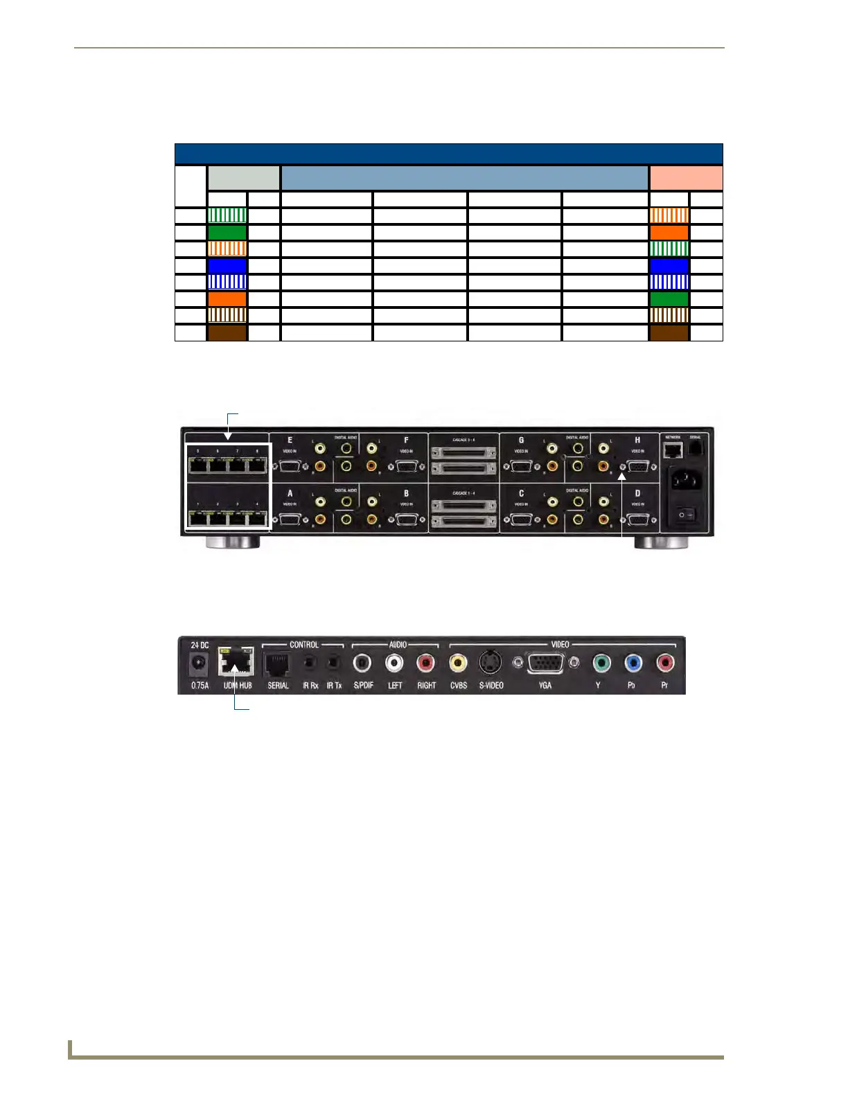
The following table provides detailed pinout information for the UDM port:
Connecting the UDM-RX02N to a UDM-0808-SIG Hub
The UDM-0808-SIG Hub features eight UDM OUTPUT RJ45 connectors, each of which support one UDM-
RX02N. The UDM-RX02N will then be connected to a display device.
1. Connect a UTP patch cable to the appropriate UDM OUTPUT RJ45 connector. The UDM-0808-SIG is
marked with the port number for each output (1- 8).
2. Connect the other end of the UTP patch cable to the UDM HUB port on the UDM-RX02N.
3. When the power is switched on, two LEDs will be visible at the UDM HUB port:
UDM Port LEDs
2 LEDs are visible at the UDM HUB port on the UDM-RX02N, when the Hub is switched on:
Green - Audio/Control Communication from UDM Hub (if UTP patch cable is removed, LED
switches off)
Amber - Power
A/V Transmission Over UTP (UDM)
RJ45
Pin #
568A
Termination
A/V Signals 568B
Termination
Color Pair # RGB YPbPr CVBS S-Video Color Pair #
1 3 Red + Y + CVBS S1 + Y + 2
2 3 Red - Y - CVBS S1 - Y - 2
3 2 Blue + Pr + CVBS S3 + C + 3
4 1 Green + Pb + CVBS S2 + 1
5 1 Green - Pb - CVBS S2 - 1
6 2 Blue - Pr - CVBS S3 - C - 3
7 4 Audio, Data, Power + Audio, Data, Power + Audio, Data, Power + Audio, Data, Power + 4
8 4 Audio, Data, Power - Audio, Data, Power - Audio, Data, Power - Audio, Data, Power - 4
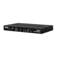
FIG. 35 UDM-0808-SIG - UDM OUTPUT connectors
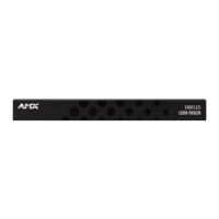
FIG. 36 UDM-RX02N Hub and Serial Ports
UDM OUTPUT Ports 1-8 (RJ45)
UDM-0808-SIG (rear panel)
 Loading...