UDM-RX02N Wiring and Connections
47
UDM-0808-SIG, UDM-RX02N and UDM-ABB-8-SIG Operation /Reference Guide
1. Connect an S-Video cable (FG-UDM-SVID01) to the 4 pin S-Video connector (FIG. 47) on the UDM-
RX02N.
2. Run the other end of the S-Video cable to the S-Video connector on the display device and establish a
firm connection.
3. If the display device has audio feeds, connect its audio to the audio connectors on the UDM-RX02N.
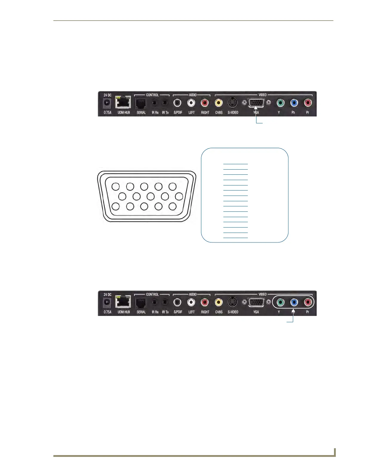
VGA Video Output Port
FIG. 49 provides the pin layout for the VGA HD15 Connector:
1. Attach one end of the VGA cable to the UDM-RX02N’s VGA connector.
2. Run the other end to the VGA connector on the display device and make a firm connection.
3. If the display device has audio feeds, connect its audio to the audio connectors on the UDM-RX02N.
Component (Y/Pb/Pr) Video Output Port
1.
Attach the Component cables to the Y (green), Pb (blue) and Pr (red) connectors on the UDM-RX02N.
2. Run the other end of the Component cable to the Component connectors on the display device and make
sure of a firm connection.
3. If the display device has audio feeds, connect its audio to the audio connectors on the UDM-RX02N.
FIG. 48 UDM-RX02N - VGA Port
FIG. 49 VGA HD15 Connector
FIG. 50 UDM-RX02N - Component Ports
12345
678910
1112131415
HD15 Pinouts
Input Pin
1
2
3
4
5
6
7
8
9
10
11
12
13
14
15
VGA
Red
Red - Ground
Green
Green - Ground
Blue
Blue - Ground
Horizontal Synch
Vertical Synch
n/c
n/c
n/c
n/c
n/c
n/c
n/c
Component Video Output Ports
 Loading...