38
Version 4.2 rev 06 Oct 2020
8.2 x 8.2 mm / 512 x 512 sensor
Lowest Noise Imaging EMCCD
Mechelle
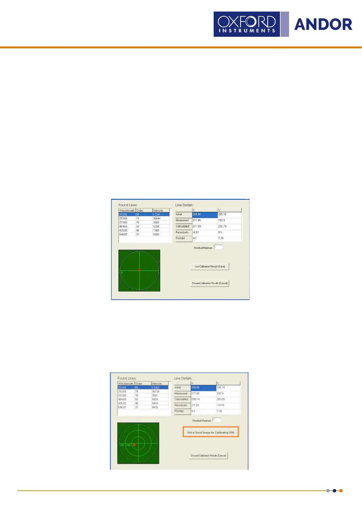
The Found Lines table (see the previous page and Figure 15 below), contains the calibration wavelengths and their
order numbers. The third column represents the intensity of this line in counts.
The table on the right-hand side, entitled Line Details, shows initial, measured and calculated positions of a given
calibration lines. All co-ordinates are in units of the pixel size. The initial position of the lines as calculated from the “old”
set of wavelength calibration constants, i.e. calculated from previous calibration.
The second row contains the measured pixel co-ordinates and the third row contains the pixel co-ordinates calculated
from the “new” (not yet stored) wavelength calibration constants.
The fourth row contains the residuals, i.e. the difference between the calculated and measured co-ordinates.
The fth row shows the full width half maximums calculated for each of the lines.
The residuals, both in the horizontal (X) and vertical (Y) directions, are plotted in a diagram. The size of the plotted area
equals the size of the search window.
If one line calibration le is used, the residuals (in X and Y direction) equal zero.
The optimum wavelength calibration is performed if the selected “calibration wavelength le” contains several (≥5) lines,
as shown:
Figure 15: Calibration results screen for 6 lines
A good calibration based on several lines should have a maximum residual of less than one pixel in the x and y
directions for lines within the echellogram funnel. Lines outside the funnel are used for extra calibration accuracy, but
the spectrum is only extracted from within the funnel; lines outside the funnel may have residuals slightly greater than
1 pixel. If the red dot on the target moves away from the centre of the cross-hairs when the Found Lines are tabbed
down, the calibration is unsuccessful and must be discarded. This plot is the graphical representation of the Residuals
values from the Line Details section. The calibration is accepted by pressing the Use Calibration Result (Save) button.
If residuals are bigger than Residuals Maximum, the software will not allow the calibration to be saved.
Figure 16: Example showing unsuitable caibration