S3xxE MM PN: 10580-00253 Rev. J 6-1
Chapter 6 — Assembly Replacement
6-1 Opening the Site Master Case
This procedure provides instructions for opening the Site Master case. With the case opened, the internal
assemblies can be removed and replaced, as detailed in the following sections.
1. Remove the battery door and battery as shown in Section 5-2 “Battery Pack Removal and Replacement ”
on page 5-2.
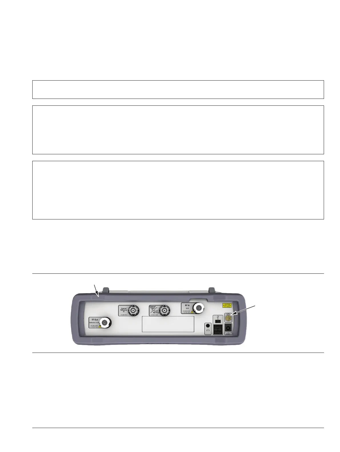
2. Remove the top and bottom bumpers (Figure 6-1) to expose the screw holes on the back of the unit.
3. Place the Site Master face down on a stable work surface that will not scratch the display.
Note
Many of the procedures in this section are generic, and apply to many similar instruments. Photos
and illustrations used are representative and may not match your instrument.
Caution
Only qualified personnel should open the case and replace internal assemblies. Assemblies shown
in Tabl e 1-4 are typically the only items that may be replaced. Because they are highly fragile, items
that must be soldered may not be replaced without specialized training.
Removing RF shields from PC boards or adjustment of screws on or near the shields may detune
sensitive RF circuits and will result in degraded instrument performance. All work should be
performed in a static-safe work area.
Caution
Electrostatic Discharge (ESD) can damage the highly sensitive circuits in the instrument.
Repair of damage that is found to be caused by electrostatic discharge is not covered under
warranty.
The Site Master contains components that can be easily damaged by electrostatic discharge (ESD).
An ESD safe work area and proper ESD handling procedures that conform to ANSI/ESD
S20.20-1999 or ANSI/ESD S20.20-2007 is mandatory to avoid ESD damage when handling
subassemblies or components found in the instrument.
Figure 6-1. Top Bumper and Option 31
Top Bumper
GPS Connnector
for Option 31
 Loading...