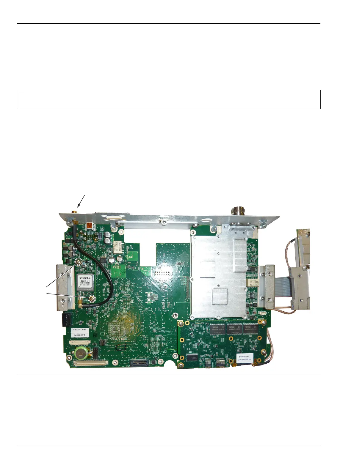
6-5 GPS (Opt. 31) Replacement Assembly Replacement
6-6 PN: 10580-00253 Rev. J S3xxE MM
6-5 GPS (Opt. 31) Replacement
This procedure provides instructions to replace the GPS assembly.
1. Open the case as described in Section 6-1 “Opening the Site Master Case”.
2. Remove the PCB assembly from the front panel as described in Section 6-2 “PCB Assembly Removal”.
3. Remove the SPA assembly as described in Section 6-3 “SPA Assembly Replacement”.
4. Use a 5/16 inch wrench to remove the nut and washer from the GPS SMA connector. Push the connector
through the top panel.
5. Remove the 2 screws retaining the GPS PCB to the Motherboard.
6. Carefully lift straight up on the GPS PCB to remove. The back of the GPS PCB is directly connected to
the Motherboard.
7. Installation is the reverse of removal.
Note
The SPA to DSP cables and the DSP PCB do not need to be removed when replacing the GPS
Module. Remove the screws securing the SPA to the bracket and move the SPA to the side.
Figure 6-8. Removing the GPS PCB from the Motherboard (SPA PCB already removed)
Remove
2 screws
Remove nut and waster
from GPS SMA connector
 Loading...