6-3 SPA Assembly Replacement Assembly Replacement
6-4 PN: 10580-00253 Rev. J S3xxE MM
6-3 SPA Assembly Replacement
This procedure provides instructions to remove the SPA assembly.
1. Open the case as described in Section 6-1 “Opening the Site Master Case”.
2. Remove the PCB assembly from the front panel as described in Section 6-2 “PCB Assembly Removal”.
3. Remove the castle nuts from the External Reference connector and the External Trigger connector
(Figure 6-5).
4. Disconnect the ribbon cable.
5. Disconnect the 2 MCX cables between the SPA PCB and the DSP PCB.
6. Remove the 6 screws securing the SPA PCB.
7. Slide the SPA PCB out of the top panel.
8. Installation is the reverse of removal. The torque setting for the 6 screws is 7.5 lbf·in (0.85 N·m).
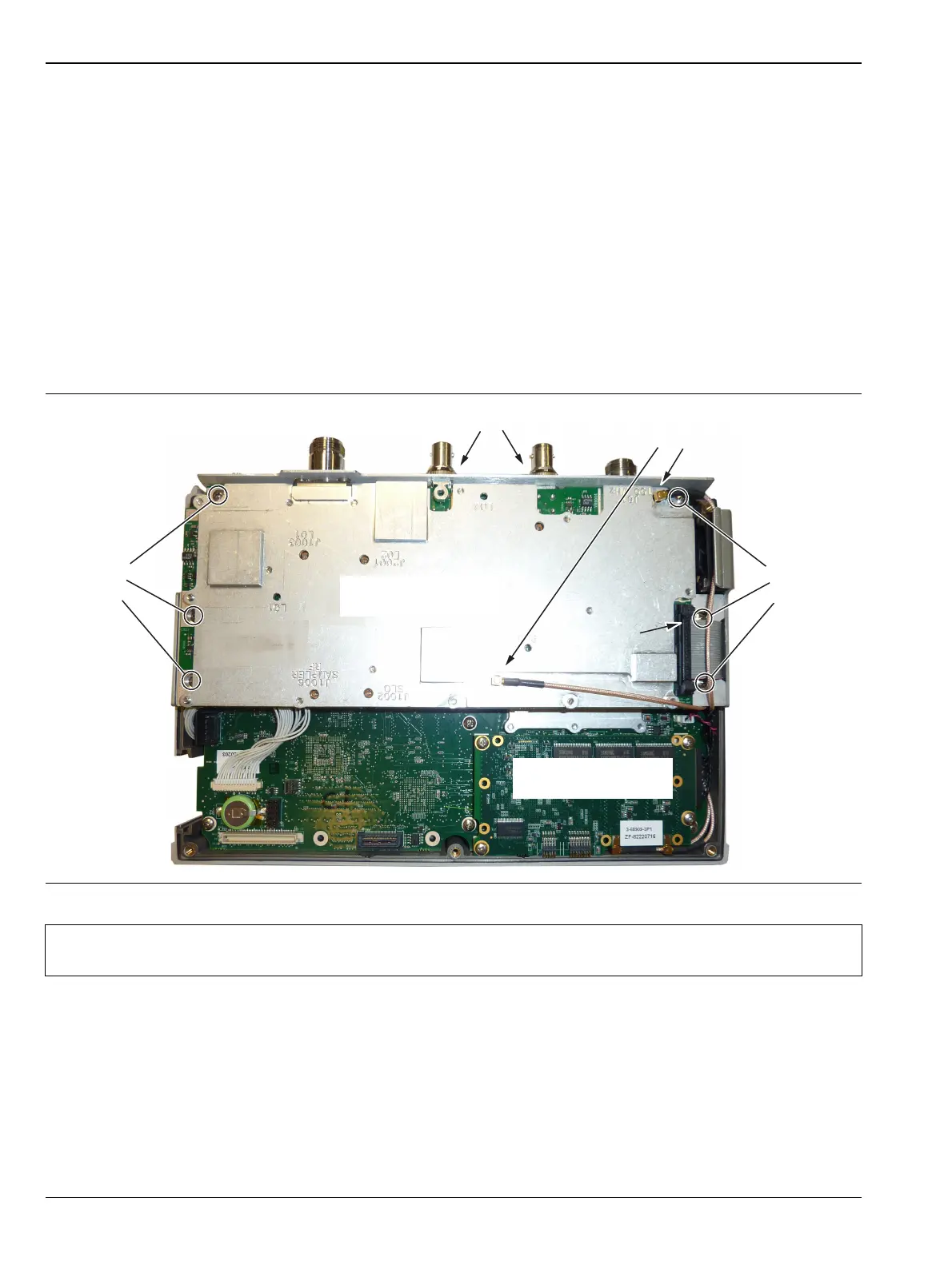
Figure 6-5. Removing the SPA Assembly
Note
The MCX cable attached to SPA connector J61 (100 MHz) is shown passing above the SPA PCB
ribbon cable. It must be routed under the ribbon cable, not as shown in Figure 6-5.
Remove
3 screws
Remove Castle Nuts
Disconnect
Ribbon Cable
Disconnect
MCX Cables
SPA Board
Remove
3 Screws
DSP Board
 Loading...