Assembly Replacement 6-2 PCB Assembly Removal
S3xxE MM PN: 10580-00253 Rev. J 6-3
6-2 PCB Assembly Removal
This procedure provides instructions to remove the Motherboard/VNA and SPA (if installed) from the
Site Master case.
1. Open the case as described in Section 6-1 “Opening the Site Master Case”.
2. Disconnect the keypad PCB cable, the fan assembly cable, and the LCD cable.
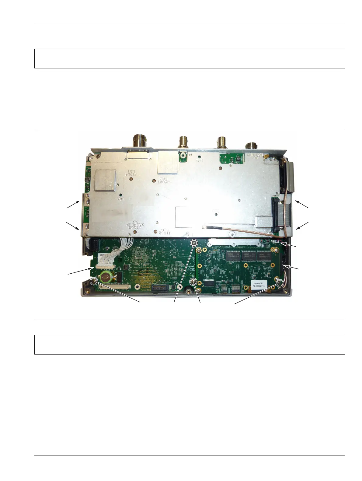
3. Use a Phillips screwdriver to remove the 8 screws securing the assemblies to the case (Figure 6-4).
4. After the screws are removed the entire assembly (including the top connector panel) can slide out of the
case.
5. Installation is the reverse of removal. Take care to properly fit the connector panel into the grooves in the
top of the case and confirm none of the cables will be pinched when the back case is replaced. The torque
setting for the 8 screws securing the PCB assembly to the front case is 7.5 lbf·in (0.85 N·m).
Note
Procedures in this section are generic, and apply to many similar instruments. Photos and
illustrations of assemblies are representative, actual assemblies may vary.
Figure 6-4. Removing the PCB Assembly out of the Case
Note
The MCX cable attached to SPA connector J61 (100 MHz) is shown passing above the SPA PCB
ribbon cable. It must be routed under the ribbon cable, not as shown in Figure 6-4.
Disconnect
Keypad PCB
Cable
Remove
2 screws
on side
Remove
2 screws
on side
Disconnect
Fan Cable
Disconnect
LCD Cable
Remove 4 screws on the Motherboard
 Loading...