Assembly Replacement 6-6 Option Assembly Replacement
S3xxE MM PN: 10580-00253 Rev. J 6-7
6-6 Option Assembly Replacement
This procedure provides instructions to replace the Ethernet (Option 411) or CPRI (Option 751) assembly.
1. Open the case as described in Section 6-1 “Opening the Site Master Case”.
2. Remove the PCB assembly from the front panel as described in Section 6-2 “PCB Assembly Removal”.
3. Remove the SPA PCB (if installed) as described in Section 6-3 “SPA Assembly Replacement”.
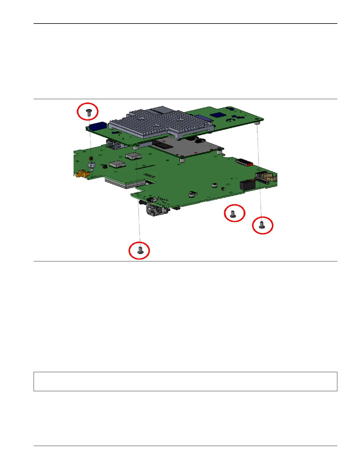
4. Remove the screws securing the Option PCB to the Main PCB as shown in Figure 6-9.
5. Installation is the reverse of removal.
6-7 Motherboard/VNA Assembly Replacement
This procedure provides instructions to replace the Motherboard/VNA assembly.
1. Open the case as described in Section 6-1 “Opening the Site Master Case”.
2. Remove the PCB assembly from the front panel as described in Section 6-2 “PCB Assembly Removal”.
3. Remove the SPA PCB (if installed) as described in Section 6-3 “SPA Assembly Replacement”.
4. Remove the GPS PCB (if installed) as described in Section 6-5 “GPS (Opt. 31) Replacement”
5. Remove the Option PCB (if installed) as described in Section 6-6 “Option Assembly Replacement”.
6. Installation is the reverse of removal.
Figure 6-9. Remove Screws Securing Option PCB to Main PCB
Note
When ordering the Main/VNA PCB assembly all options that are installed on the instrument must be
stated on the order.
 Loading...