6-11 Keypad and Keypad PCB Replacement Assembly Replacement
6-12 PN: 10580-00253 Rev. J S3xxE MM
6-11 Keypad and Keypad PCB Replacement
This procedure provides instructions to replace the rubber keypad and the keypad PCB.
1. Open the case as described in Section 6-1 “Opening the Site Master Case”.
2. Remove the PCB assembly from the front panel as described in Section 6-2 “PCB Assembly Removal”.
3. Perform Step 1 through Step 4 of Section 6-9 “LCD Assembly Replacement”.
4. Remove the 8 screws and the cables attached to the keypad PCB allowing removal of the keypad PCB
(Figure 6-15). The rubber keypad is located under the keypad PCB.
5. Reverse the above steps to install the replacement rubber keypad and/or keypad PCB.
6. The keypad PCB stores the touch screen calibration data. If the keypad PCB is replaced, then a touch
screen calibration must be performed. If no touch screen calibration data is stored in the new keypad
PCB when powering on a unit, it will stay at the boot up screen with the Anritsu logo shown and a
message at the bottom of the screen stating:
Failed to load touch screen calibration data. Please reboot the instrument.
If this message is displayed, power off the unit and power the unit on in bootstrap mode by pressing and
holding down the Shift - 4 - 0 keys while pressing the power on button. Now the unit will boot up in
bootstrap mode and prompt you to perform a touch-screen calibration. After following the on-screen
calibration directions, power the unit off and it will boot up correctly on the next power cycle.
7. If the keypad PCB was replaced with a PCB that has touch screen calibration data, the unit will boot up
properly, but the touch-screen calibration data may not be accurate. Perform a touch-screen calibration
by pressing the Shift key and then the 0 key, and follow the on-screen calibration directions.
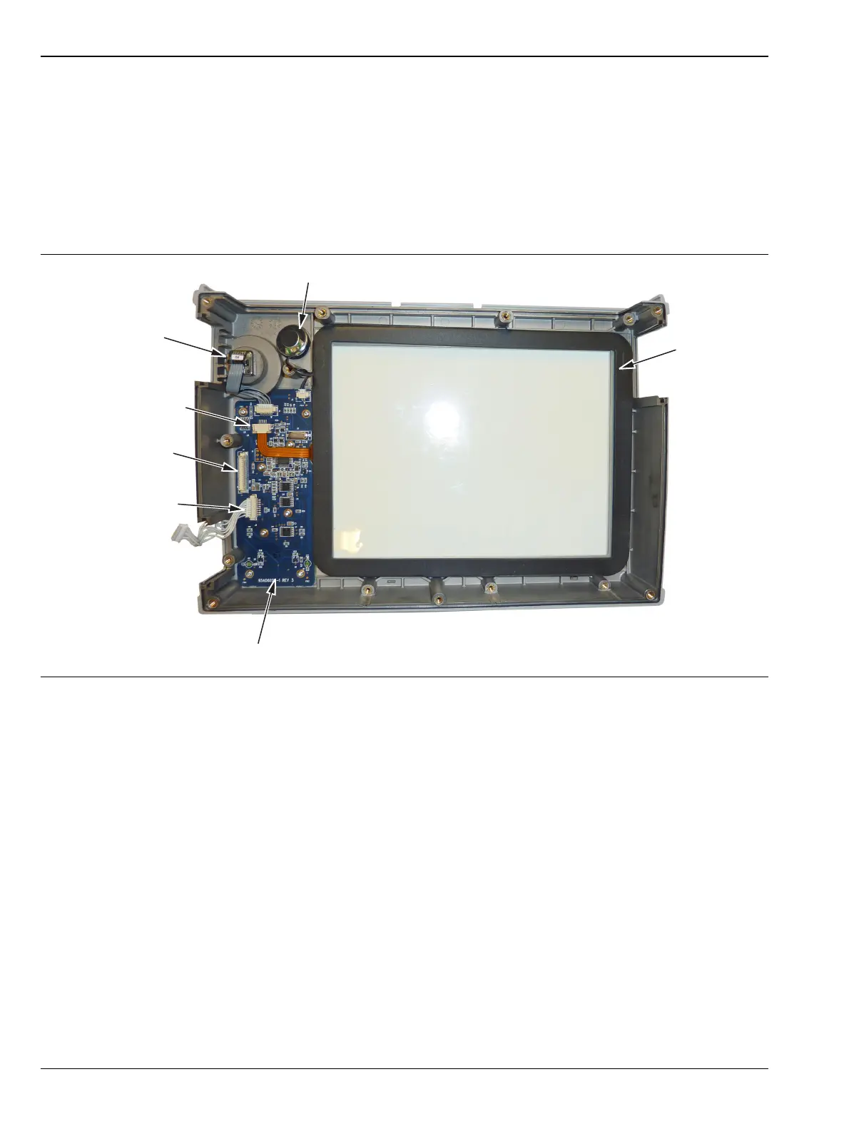
Figure 6-15. Front Panel Keypad Bezel
Speaker
Rotary Knob
Encoder
Touch Screen
Connector
Touch Screen
Keypad Switch
Connector
Keypad PCB (Remove 8 Screws)
Backlight PCB
Connector
 Loading...