2-7 Displayed Average Noise Level (DANL) Spectrum Analyzer Verification
2-16 PN: 10580-00253 Rev. J S3xxE MM
2-7 Displayed Average Noise Level (DANL)
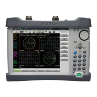
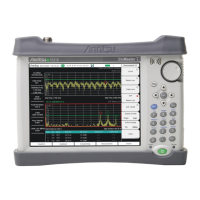
The following test is used to verify the Displayed Average Noise Level (DANL) of the spectrum analyzer
systems in the S332E and S362E Site Master. This test is performed using the RMS detection mode.
Equipment Required
• Anritsu 28N50-2 50 ohm Termination
Procedure
1. Connect the 50 ohm Termination to the S332E or S362E Spectrum Analyzer RF In connector.
2. Press the On/Off key to turn on the S332E or S362E Site Master.
3. On the S332E or S362E, press the Shift key and then the Mode (9) key. Rotate the knob to highlight
Spectrum Analyzer and then press the Enter key to switch to Spectrum Analyzer mode.
4. Press the Shift key, the Preset (1) key, and then the Preset soft key to reset the instrument to the default
starting conditions.
5. Press the Shift key, the Sweep (3) key, then the Sweep Mode soft key, and press the Performance soft key.
6. Press the Amplitude soft key, then press the Reference Level soft key.
7. Use the keypad to enter –20 and press the dBm soft key.
8. Press the Atten Lvl soft key and enter 0, then press the dB soft key.
9. Make sure that the Preamp is Off.
10. Press the Amplitude soft key, then press the Detection soft key and then the RMS/AVG soft key.
11. Press the BW soft key and press the RBW soft key.
12. Use the keypad to enter 100 and press the kHz soft key.
13. Press the VBW soft key.
14. Use the keypad to enter 1 and press the kHz soft key.
15.
Press the Freq soft key and press the Start Freq soft key.
16. Use the keypad to enter 10 and press the MHz soft key.
17. Press the Stop Freq soft key, enter 2.4 and press the GHz soft key.
18. Wait until one sweep is completed.
19. Press the Marker soft key and then press Peak Search soft key.
20. Record the Marker reading to the test records. Use the Measured Value @ 100 kHz RBW column of
Table A-11, “Spectrum Analyzer DANL with Pre Amp Off”.
21. Repeat Step 15 through Step 20 for the other frequency settings in Table A-11 that are applicable for the
unit under test. Change the VBW setting as indicated in the VBW column of Table A-11.
22. For each measured 100 kHz RBW value in the test record, convert it to 10 Hz RBW value by subtracting
40 dB.
–100 dBm – 40 dB = –140 dBm
Note Before continuing, allow a 30 minute warm up period for the internal circuitry to stabilize.
Note
The noise floor consists of totally random signals where a spur is a fixed spike of varying amplitude
that is always visible.
 Loading...


