6-8 Fan Assembly Replacement Assembly Replacement
6-8 PN: 10580-00253 Rev. J S3xxE MM
6-8 Fan Assembly Replacement
This procedure provides instructions to replace the fan assembly.
1. Open the case as described in Section 6-1 “Opening the Site Master Case”.
2. Remove the PCB assembly from the front panel as described in Section 6-2 “PCB Assembly Removal”.
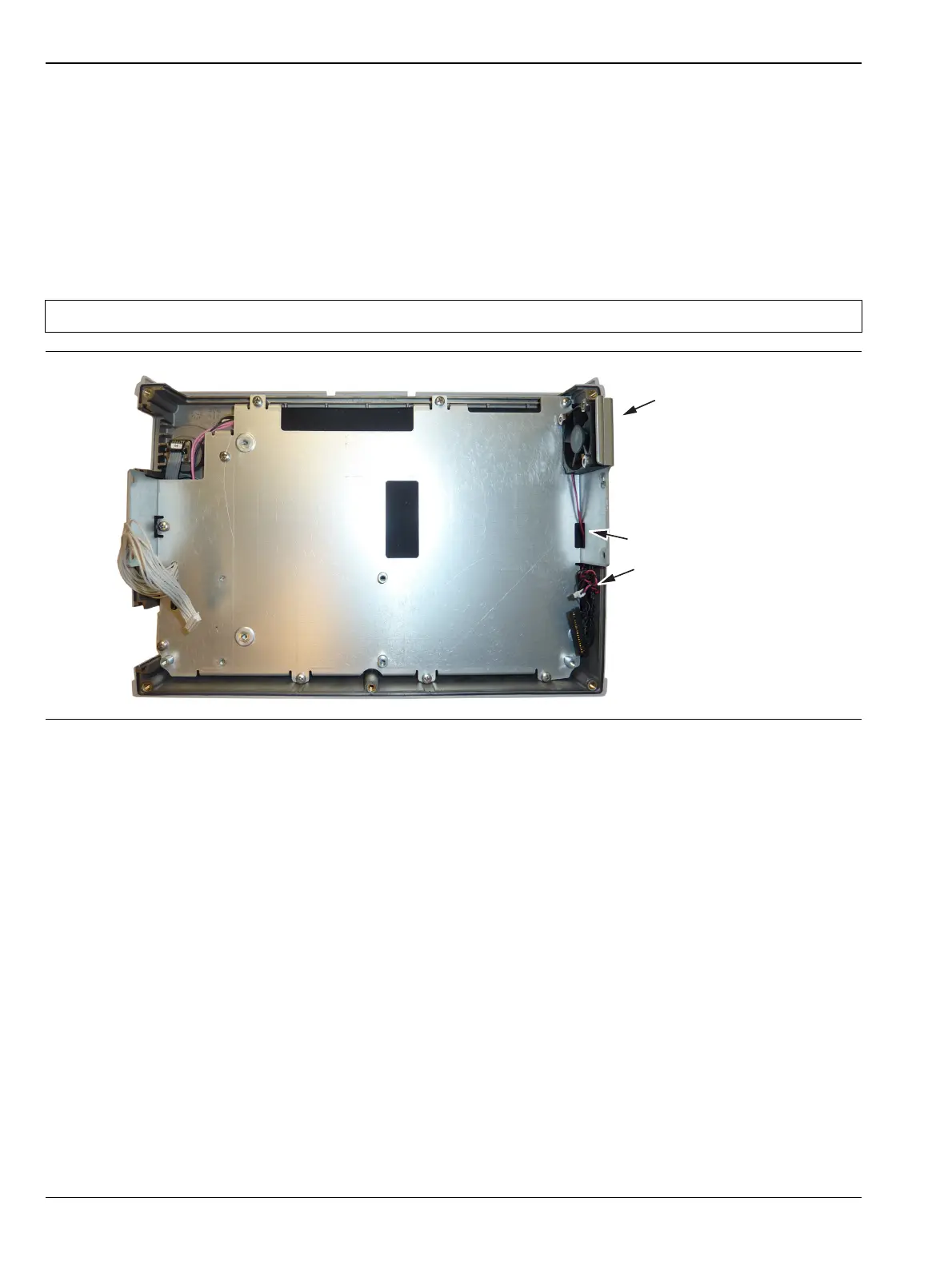
3. The fan is attached to the LCD housing by either three screws or three rubber mounts. If screws are used,
remove the screws to remove the fan and re-use the existing screws to secure the replacement fan. If
rubber mounts are used, cut the rubber mounts in order to remove the fan, and new rubber mounts will
be included with the replacement fan assembly. Refer to (Figure 6-10).
4. Reverse the above steps to install the replacement fan assembly.
Note The fan connector cable is routed through the LCD housing
Figure 6-10. Front Panel Showing Fan Assembly
Fan Assembly
Fan Connector cables
go though the LCD
Assembly housing
 Loading...