Assembly Replacement 6-10 LCD Backlight PCB Removal and Replacement
S3xxE MM PN: 10580-00253 Rev. J 6-11
6. Disconnect the LCD backlight cable from the LCD backlight PCB.
7. Disconnect the LCD cable from the side of the LCD.
8. Carefully remove the LCD.
9. Reverse the above steps to install the replacement LCD.
6-10 LCD Backlight PCB Removal and Replacement
This procedure provides instructions to replace the Site Master LCD backlight PCB. (Newer units will not have
this PCB.)
1. Open the case as described in Section 6-1 “Opening the Site Master Case”.
2. Remove the PCB assembly from the front panel as described in Section 6-2 “PCB Assembly Removal”.
3. Perform Step 1 through Step 4 of Section 6-9 “LCD Assembly Replacement”.
4. Disconnect the LCD backlight cable from the LCD backlight PCB.
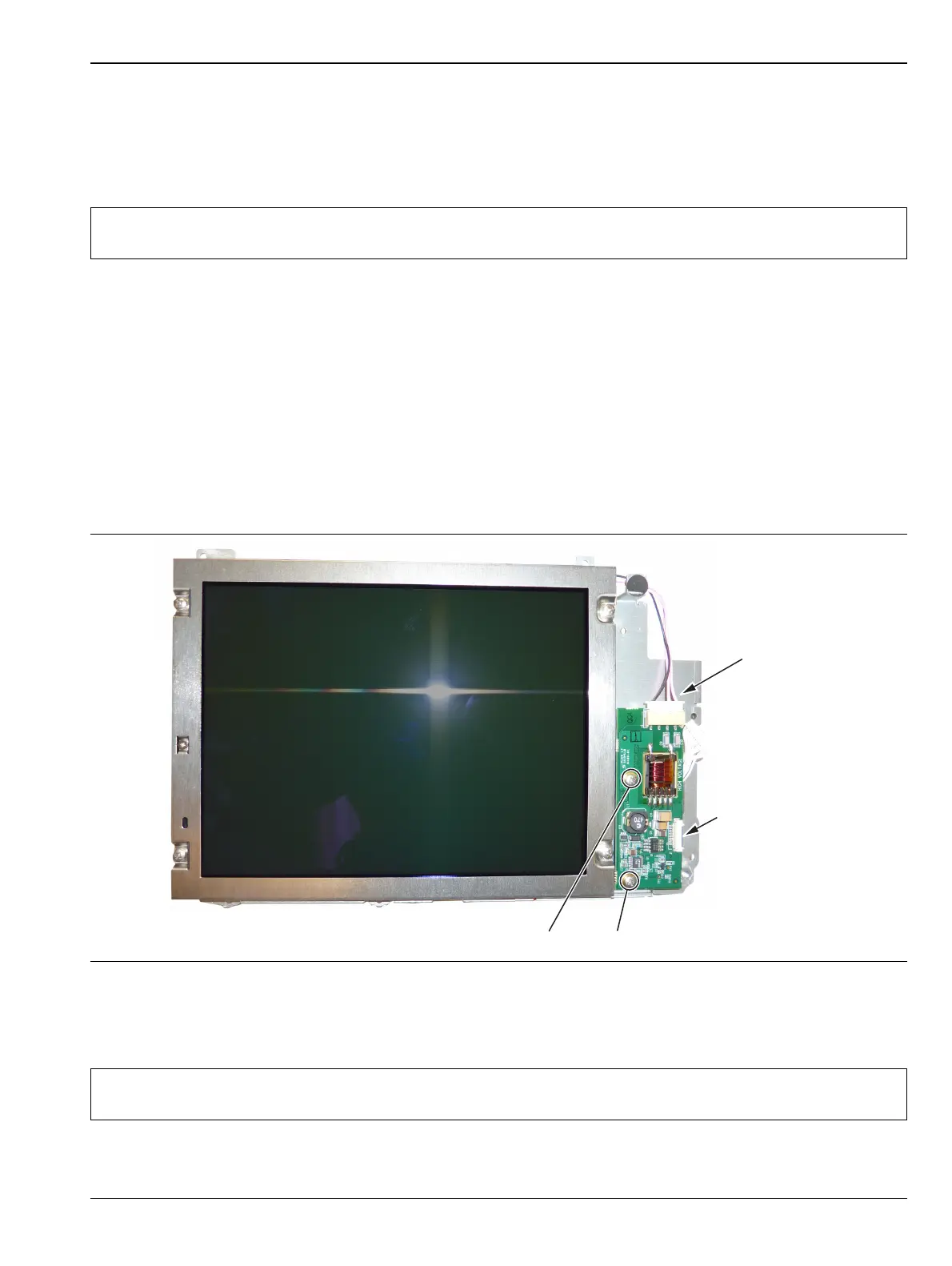
5. Use a Phillips screwdriver to remove the two screws securing the LCD backlight PCB to the LCD bracket
(Figure 6-14).
6. Carefully remove the LCD Backlight PCB.
7. Reverse the above steps to install the replacement LCD Backlight PCB.
Note
Pay attention to the routing of the LCD Backlight Cable. The cable must be positioned so it is not
pinched when the unit is reassembled.
Figure 6-14. Replacing the LCD PCB
Note
Pay attention to the routing of the LCD Backlight Cable. The cable must be positioned so it is not
pinched when the unit is reassembled.
Remove 2 screws to replace LCD PCB
LCD Backlight
Cable
Ribbon Cable
Connects to
Keypad PCB
 Loading...