2-7 Connector Panel Instrument Overview
2-16 PN: 10580-00251 Rev. T MS2712E/13E User Guide
External Reference In
The External Reference In port is a 50 Ω BNC female connector that provides for input of an
external frequency reference. Refer to your Technical Data Sheet for valid frequencies. To
prevent damage to your instrument, do not use pliers or a wrench to tighten the BNC
connector.
External Trigger In
A TTL signal that is applied to the External Trigger female BNC input connector causes a
single sweep to occur. In the Spectrum Analyzer mode, it is used in zero span, and triggering
occurs on the rising edge of the signal. After the sweep is complete, the resultant trace is
displayed until the next trigger signal arrives.
Analyzer/RF In
50 Ω Type-N female connector. Maximum input is +33 dBm at 50 VDC.
USB Interface – Mini-B
The USB 2.0 Mini-B connector can be used to connect the Spectrum Master directly to a PC.
The first time the Spectrum Master is connected to a PC, the normal USB device detection by
the computer operating system will take place.
GPS Antenna Connector (Option 31)
The GPS antenna connection on the Spectrum Master is type SMA-female. GPS function is
described in Chapter 6, “GPS (Option 31)”.
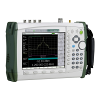
Figure 2-16. RJ45 Ethernet Connector (Option 411)
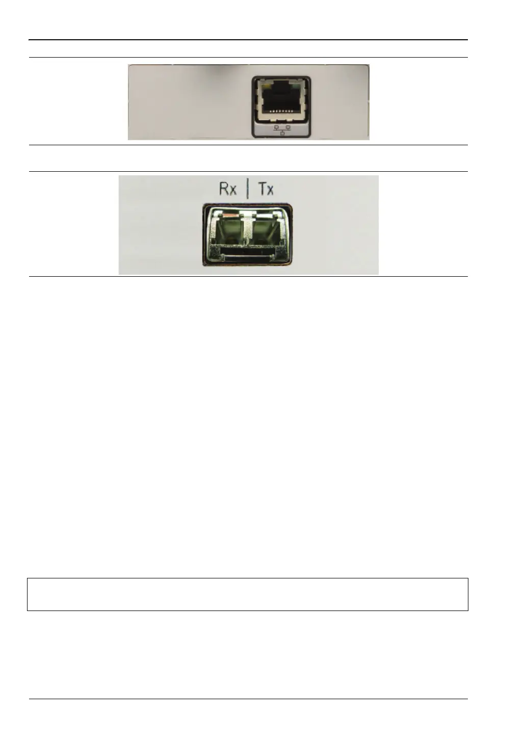
Figure 2-17. Optical Module Connector (Option 751)
Note
For proper detection, the applicable Anritsu Software Tool should be installed on
the PC prior to connecting the Spectrum Master to the USB port.