Instrument Overview 2-7 Connector Panel
MS2712E/13E User Guide PN: 10580-00251 Rev. T 2-15
2-7 Connector Panel
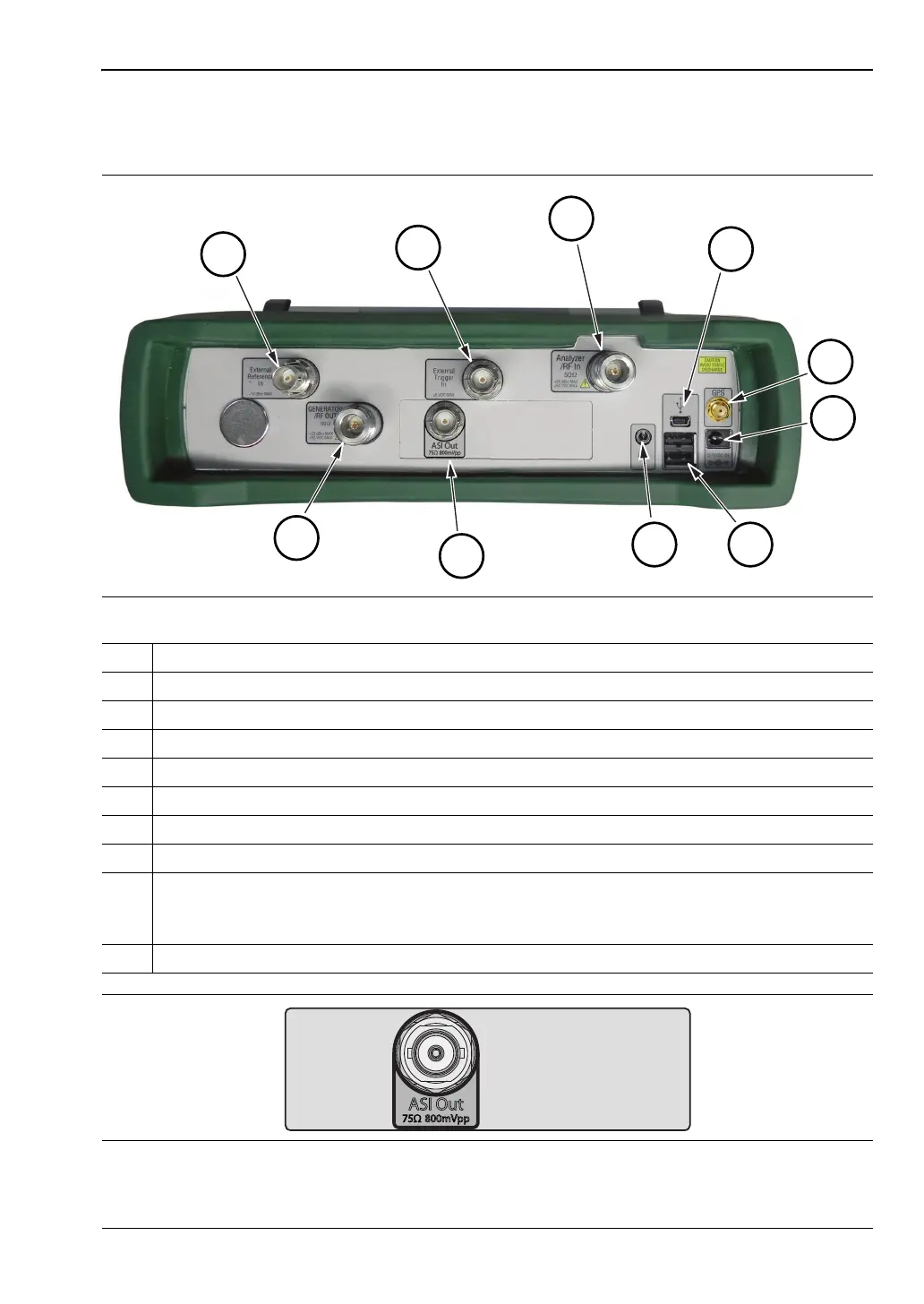
The Spectrum Master connector panel is illustrated in Figure 2-14.
Figure 2-14. Spectrum Master Connector Panel
1. External Reference In
2. External Trigger In
3. Analyzer/RF In (Type N)
4. USB Mini-B
5. GPS Type SMA (Option 31)
6. External Power
7. USB Type A
8. Headset jack
9. Options 57 and 79: DVB ASI Out Connector (see Figure 2-15)
Option 411: RJ45 Ethernet Connector (see Figure 2-16)
Option 751: SFP Optical Module Connector (see Figure 2-17)
10. Generator/RF Out Type N (Option 20)
Figure 2-15. DVB ASI Out BNC Connector for BER Measurements (Option 57 and Option 79)