GT300 Installation
IMGT30017EN 31
3A.4 Reactors
3A.4.1 Input line reactors
An AC line reactor can be used, provided it meets IEEE 587 standards for transient protection. The reactor causes a voltage drop proportional to
the supply current and to the inductance value; select a reactor to have a voltage drop equal to 2 – 5 % of the rated input voltage (when the drive is
conducting full rated current).
Line Reactor Function:
• Reduces RMS ripple currents in bus capacitors • Protects against unbalanced and signal phase condition
• Protects the drive from line side transients • Improves the true power factor
• Reduces nuisance tripping from input voltage spikes • Reduces input current harmonics
• Provides RFI suppression
Input Line reactors absorb power line disturbances that could otherwise damage or shutdown the drive or other sensitive equipment.
Line Reactors reduce generated harmonics helping to meet the IEEE-519, 1993 guidelines for harmonic limitation.
The GT3000 frame IIIN, IVN, VN, VIN 6p AC power supply have a 2,5% internal reactor, other frames needs input reactor between mains and drive if:
A a thyristor converter or other drives are operating on the same line.
B power factor correction capacitors are connected to the same line.
C the supply voltage unbalance exceeds 3%.
Example: Vrs = 400V, Vst = 407V, Vtr = 390V.
V
V V V
3
399VM
rs st tr
2,3%
399
9
100
V
Vfromdeviationmax.
100F
M
M
s
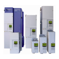
D The supply line power and the drive power are included in the highlighted area:
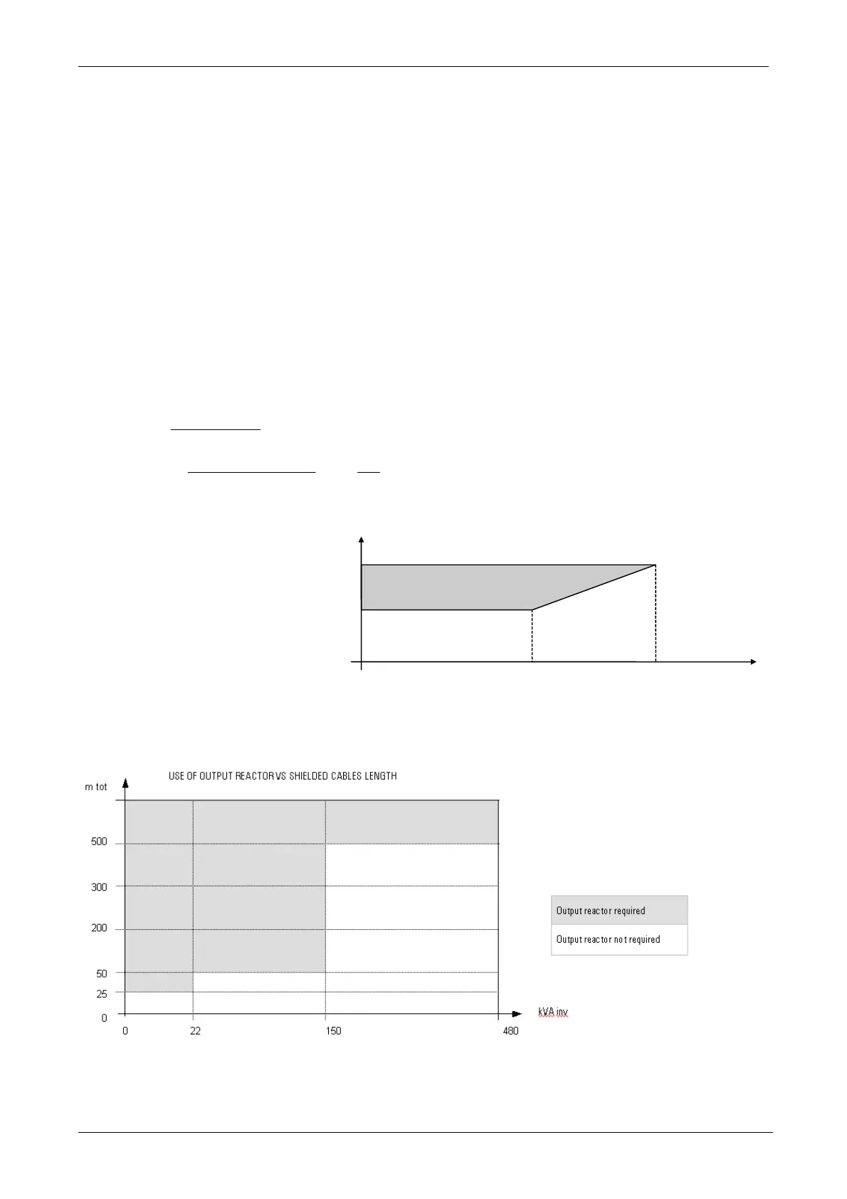
3A.4.2 Output reactors
Waveform generation from a typical pulse width modulated (PWM) motor drive has the potential to excite motor cable resonance-producing
voltages in excess of 3 to 3 times the DC bus voltage at the motor terminals. The GT3000 product line was designed to compensate the capacitive
dispersion current to ground and to reduce the voltage gradient on the motor. Reactors, together with the ferrite cores, help RFI phenomena
attenuation.
CAUTION: In case of motors in parallel, it is necessary to take into account the sum of the lengths of all motor cables
Limit the length of the motor cables so as not to exceed a voltage drop of 3 ÷ 5 % at the rated current.
NOTE: The input reactor and output reactors codes are in table 3A.5
500
2500
Supply line power
50
Drive size
[kVA]
[kVA]
Vrs, Vst, Vtr : rms value of line-to-line voltages
Vm : mean value of Vrs, Vst, Vtr
Fs : voltage unbalance
In this example a reactor is not necessary