Installation GT3000
34 IMGT30017EN
Table 3A.5.1.1 Microprocessor basic control terminal block
Warning: Do not connect voltage signals higher than 24 VDC to input connections
Function XM1 Label Description
1 RL2 Prog NO
Configurable Output 1A-250V
2 RL2 Prog Com
18 RL1 Fault NO
“FAULT” fixed output 1A-250V
Relay
19 RL1 Fault Com
3 Channel B
4 Channel /B
5-12-24V (1024 PPR). With line driver encoder at 5V set SW1_B to ON ( 121 load
resistor connected to encoder output signals)
5 Channel A
6 Channel /A
5-12-24V (1024 PPR). With line driver encoder at 5V set SW1_C to ON (121 load
resistor connected to encoder output signals )
22 Channel Z
Encoder
23 Channel /Z
(If necessary) 5-12-24V. With line driver encoder at 5V set SW1_D to ON (121 load
resistance connected to encoder output signals)
20 Encoder +5V
150mA – 5V isolated encoder supply - ( SW1-A = On),
External supply 12-24V (SW1-A = Off)
Encoder Power
Supply
21 Encoder gnd
0V
7 DI 1 Start/Stop
The application of +24 VDC will cause the drive to start and ramp up in speed. The removal
of +24 VDC will cause the drive to coast down and stop.
8 DI 2 Prog Programmable digital input 8mA
9
DI 8 DRIVE
ENABLE
The application of +24 VDC will allow the drive to control the IGBTs.
The removal of +24 VDC will cause, after 0,5ms, the IGBTs to stop switching.
10 DI supply +24V
24V- 100mA Digital inputs power supply. Protected with resettable fuse
11 DI / DO ground
0V digital inputs and outputs
12 Polarity Choice
l input active when connected to 24VDC
POL connected to 24V (XM1
10): digital input active when connected to 0V.
24 DI 5 Prog
25 DI 6 Prog
Programmable input 8mA
26 DI 7 Prog
27
DO 4/DI 9(
1
)
*
24V isolated input 8mA /
28
DO 5/DI 10(
1
) isolated output 10 mA - Programmable
Digital
I/O
Max 24VDC
29
D0 6(
1
) 24V isolated output 10mA –Programmable. Protected with resettable fuse
13 AI/AO ground
Common connection for analog outputs
14 AI 1+
15 AI 1-
16 AI 2+
17 AI 2-
Programmable differential input. Used for main Speed reference.
Inputs can be:
a) Through potentiometer 5-10K. (Nominal value 5k)
b) External voltage signal 10V. Input impedance 40k
c) External current signal 0/4-20mA. Input impedance 475
30 +10Vdc
+10VDC 5mA
32
AI/AO ground Common connection for analog inputs and outputs
31 -10Vdc
-10 VDC 5mA
33 AO 1
Programmable analog output 1 (PWM Output) 10V – 5mA
Potentiometer
Power Supply
34 AO 2
Programmable analog output 2 (PWM Output) 10V – 5mA
(
1)
) It is compulsory to use internal supply. External supply connected to terminal XM1-27/28/29 causes the damage of
the board.
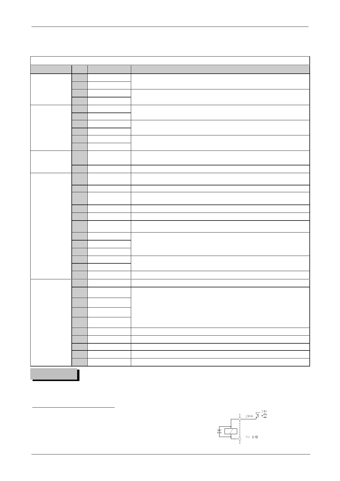
*
24V–10mA static output if the load is inductive type (relay coil), install a suitable diode in parallel
WARNING