STO Function GT3000
72 IMGT30017EN
10. make sure that the "STO" alarm procedure is activated automatically and that the operating sequence cannot be restored up until
the failure has been repaired; otherwise, check the reasons for non-identification of the failure and proceed accordingly. Restart the
verifications from § 1;
11. disable the “STO” request, restore the connection to terminal XM70-3 or XM70-4 and restore protection devices, if any;
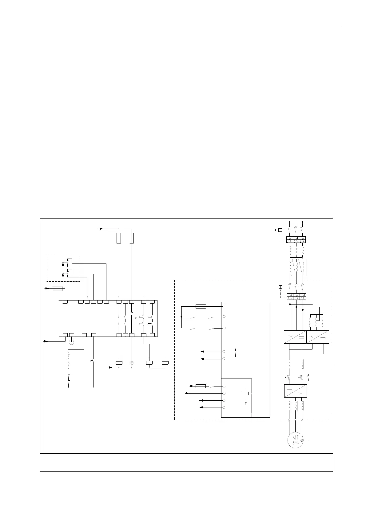
6A.6.6 Configuration example
The configuration example reported below includes:
An interlocked guard without any locking device
STO configuration according to category 3 EN 954-1
Controlled stop according to category 1 of EN 60204-1
Control outputs of inputs STO and Dren, according to category 3 or 4 of EN 954-1
Use of a safety module to control the guards, for stop category 1 according to EN 60204-1 and safety category 3 according to EN 954-1
Conductors of feedback signals (with short-circuit protection)
In case of a feedback error, automatic activation of the "STO" alarm procedure: the operating sequence cannot be restored up until the
failure is repaired
Operating sequence:
1. When the guard opens, the instantaneous output of the safety module which controls relay K1 (whose NO contact disables the RUN control)
is opened.
2. The delayed output of the safety module remains excited for the preset time (longer than the stop time required for the motor)
3. The motor slows-down in a controlled way, up until it stops.
4. Once the motor has stopped, the delayed output of the safety module which controls relays K2 and K3 (whose NO contacts disable the
Dren and STO controls) is opened.
5. Now the motor is in the "SAFE TORQUE OFF" state and cannot generate any torque. In order to stop a revolving motor with a load torque
applied to the axis, install a mechanical brake.
F0
F1
T0
T3
T1
R1
T2
L1
L2 L3 L1 L2
L3
+
3
- -+
3
R2
Q2
XM1-13
02
43
XM1-24
XM1-20
XM70-4
XM70-3
XM70-1
XM70-2
-XM70
SAFETY
TORQUE
OFF
-F
-K3
+24Vdc
N/-
-R02
FBK ENABLE
-KX
START
(*)
-F
-Q2
-K1
-K2
-T2
SCADA PLUS
(*) Opzione: START comandato via PROFIBUS
+ F401
NOTE
-i relè K2 e K3 con contatti a guida forzata secondo Norma EN50205
NOTA
-un relè o funzione equivalente per ogni azionamento
-K3
FDB STO
FDB Enable
-T2-R02
-T2-XM70
-K2
N/-
-S2
Reset
-K1
11.3
-H1
-K2
11.4
-K3
11.4
A2 PE Y33
Y34
4814 24
32
3TK2827
58
24Vdc
-F
Y10
A1
Y11 Y12 Y22
Y21 13
23
31
47
57
-F
-F
24Vdc
N/-
-a relais or equivalent function for every drive
Option: START control via PROFIBUS
STOP TYPE: CAT.1 CONTROLLED
SAFETY LEVEL EN954-1 CAT.3
DRIVE TYPE WITH SAFE TORQUE OFF
-relais K2 and K3 with forced track contacts according to
Standard EN50205
02
43
3
4
24Vdc
DI8 Drive Enable
DI1Start
Riparo interbloccato
ma privo di blocco
Safety-guard interlocked
but without lock