Cabling the Modular Switch
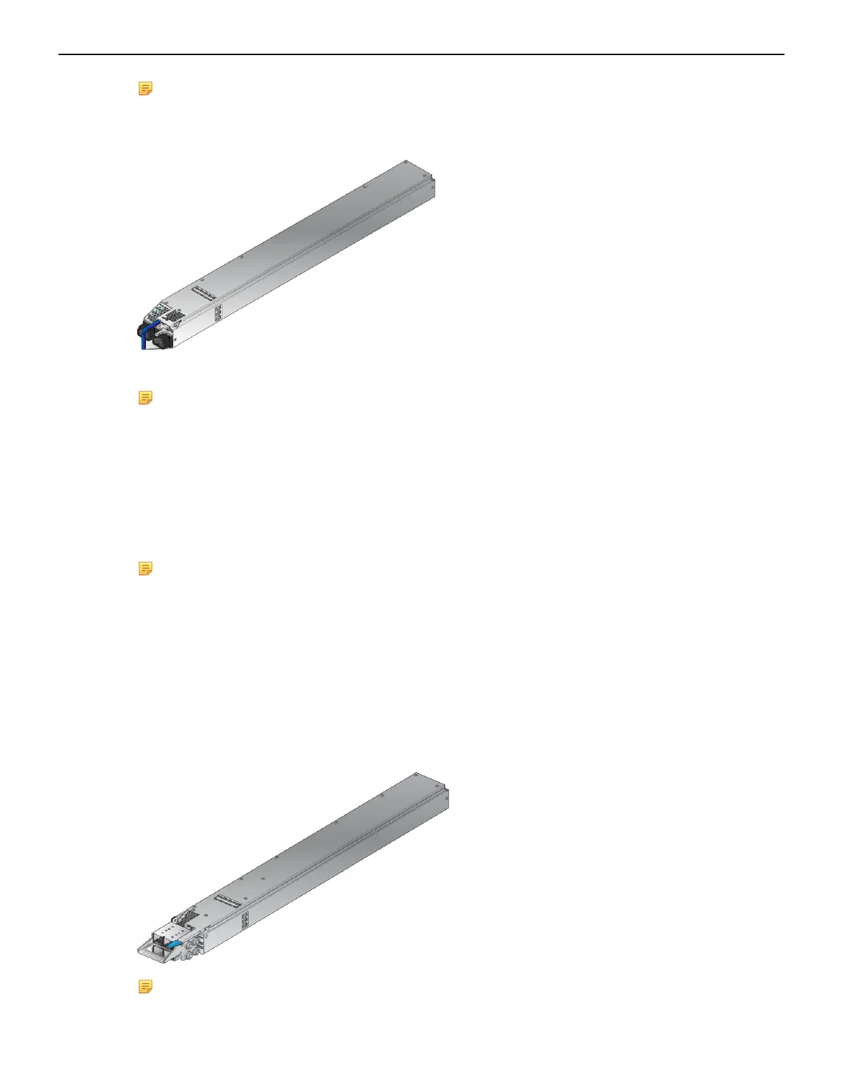
Note: The power supply, handle color, orientation, etc. may be different in your device from the
one shown in Figure 17: AC Power Supply.
Figure 17: AC Power Supply
The Front Panel displays the front panel location of the power supplies.
Note:
• The LEDs on a PSU remain lit for a period of time even after you disconnect the power and
remove the PSU from the chassis. They will eventually turn off in a short while.
• The PWR-D1-3041-AC-BLUE PSU uses 2x 220 V supply inputs and uses 2 APP SAF-D-
GRID 400 connectors.
4.4 Cabling the DC Power Supply
Note: The -48V and Battery-Return leads are a pair and should run adjacent to each other and
be approximately the same length.
Le - 48V et câbles de batterie-retour sont une paire courir à côté de l'autre et doivent être à peu
près la même longueur.
4.4.1 DC Power Supplies
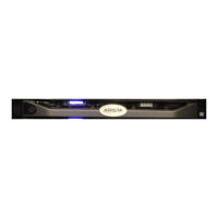
The switches support the PWR-D2-3041-DC-BLUE DC power supply displayed in Figure 18:
PWR-D2-3041-DC-BLUE Power Supplies.
Figure 18: PWR-D2-3041-DC-BLUE Power Supplies
Note: Release lever color indicates airflow direction.
29