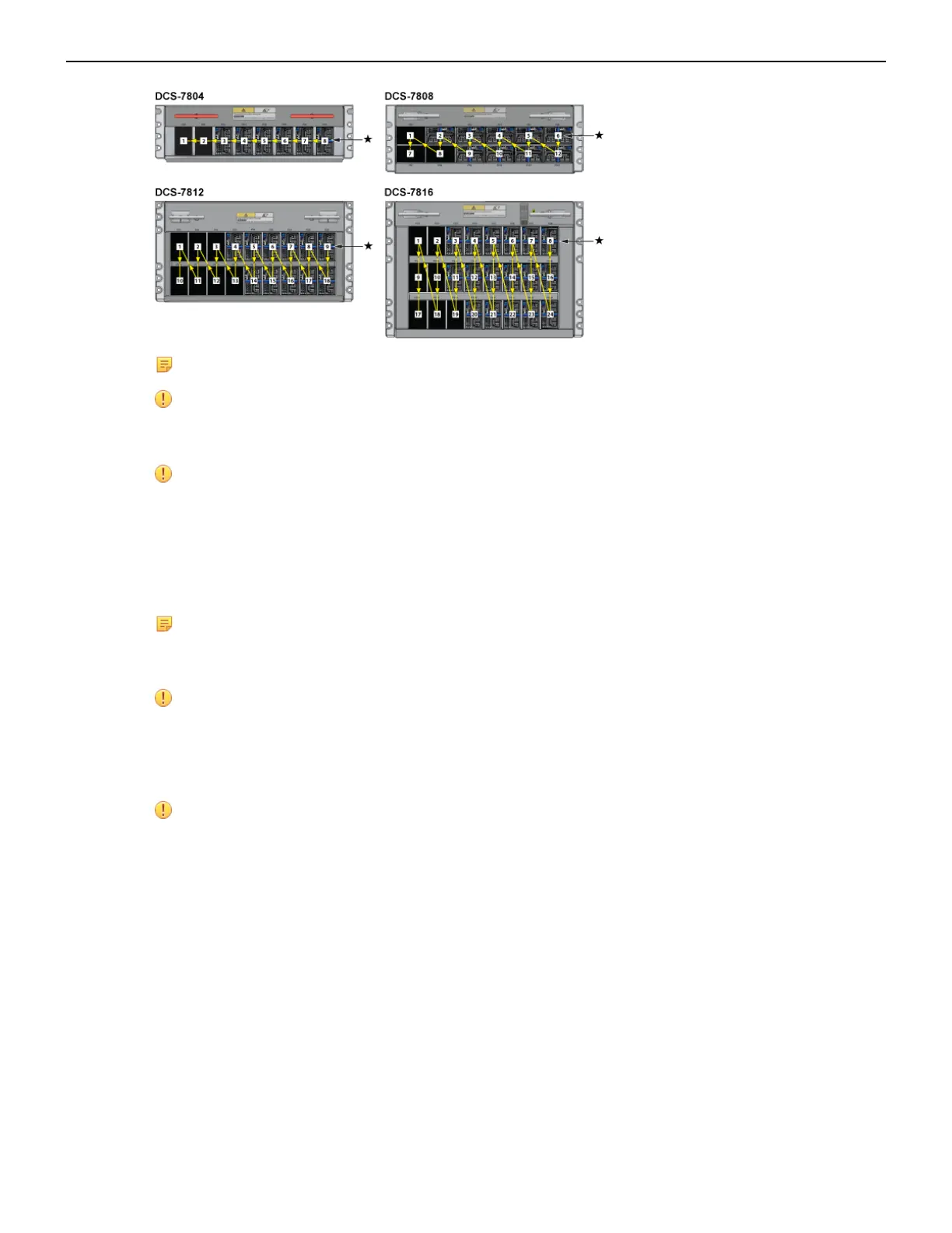
Note: '*' designates the recommended starting bay.
Important: Power down the switch: Remove all power cords from the power inlets.
Mettez le commutateur: Retirez tous les cordons d'alimentation des prises d'alimentation.
Important: Installation of this equipment must comply with local and national electrical codes.
If necessary, consult with the appropriate regulatory agencies and inspection authorities to
ensure compliance.
Installation de cet équipement doit être conformes aux codes électriques locaux et nationaux.
Si nécessaire, consulter les organismes de réglementation appropriés et des autorités de
contrôle pour assurer la conformité.
Note: Many configurations will require additional power supplies.
Nombreuses configurations exigera des alimentations supplémentaires.
Important: All power supply slots must be filled with either a power supply or blank to ensure
proper air flow.
Tous les emplacements d'approvisionnement de puissance doivent être remplis avec une
alimentation ou vide pour assurer un débit d'air appropriée.
Important: Read all installation instructions before connecting the system to the power source.
Lire toutes les instructions d'installation avant de brancher le système à la source
d'alimentation.
The Table 9: Power Supply Configurations shows the minimum number of operating power supplies
that must be connected to active circuits for each switch to operate.
Each power supply includes a fan that maintains proper power supply temperature. The appendices
display the location of components for all switches described in this guide.
4.2 Cabling Chassis Ground
The Figure 13: Front Panel (DCS-7804), Figure 14: Front Panel (DCS-7808), Figure 15: Front Panel
(DCS-7812), and Figure 16: Front Panel (DCS-7816) display the location of the chassis grounding
locations on the front panel of the switches. Chassis ground locations are also located on the rear
panel of the switch chassis. After mounting the switch into the rack, connect at least one of the chassis
24