F.1.1
Assembling and Storing the Extraction Tools
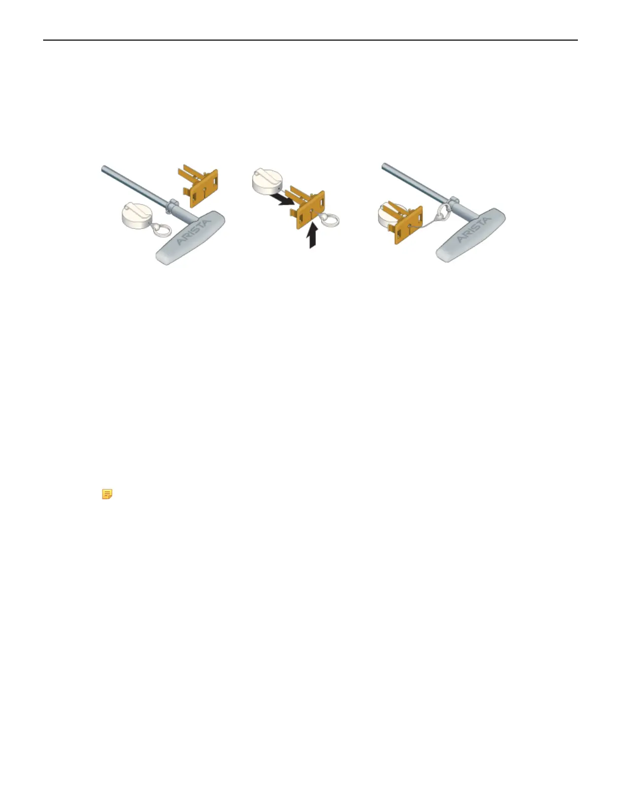
The extraction tools come with a lanyard and tethering plug as shown in Figure 43: Linecard and
Supervisor Module Extraction Tool and Tether Assembly.
Figure 43: Linecard and Supervisor Module Extraction Tool and Tether Assembly
Use the following steps to attach the tethering mechanism to the extraction tool.
1. Extend and slip the lanyard thread through the slot in the plastic tether.
2. Attach the ring to the extraction tool.
3. Plug the plastic tether into one of the slots (Figure 32: DCS-7804 Front Panel (Fully Populated)).
4. Repeat for the other tools as appropriate.
F.2
Power Supplies
The s
witches support AC or DC Power supplies. The switches ship with a number of populated
slots depending on the switch model. Empty slots are covered with a blank. For adding a new power
supply in one of the available slots, remove the blank covering the slot before inserting a new power
supply.The following steps are required for ESD protection when adding or replacing power supplies.
Note: Front Panel shows the locations of power supplies for your device.
F.2.1
1. Connect at least one of the chassis grounding pads located on the front and rear panels of the
chassis to the data center ground as needed to ensure that the switch is grounded.
2. Put on an anti-static ESD wrist strap and connect it to one of the attach points on the switch.
3. Remove the power supply to be replaced (Removing AC Power Supply, Removing DC Power
Supply) or the blank for the slot (Removing Power Supply Blank) in which the new power supply is
to be added.
Perform the following steps to remove an AC power supply.
1. Put on a grounded, anti-static ESD strap.
2. Unplug the cable(s) by squeezing the cable release. Up to two cables could be powering each PSU.
3. Squeeze the latch release.
4. Remove the power supply from the switch using the power supply latch release and handle.
62
Removing AC Power Supply