Maintenance and Field Replacement
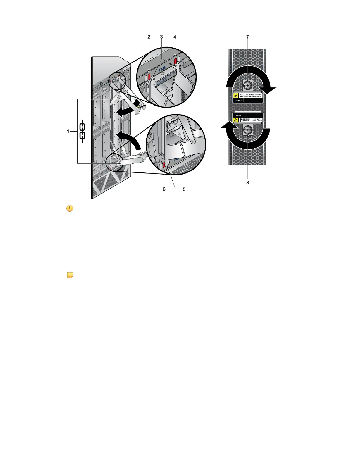
CAUTION: Ensure that the claws engage correctly on the chassis.
1 Fabric module ejector levers 4 Claw position on chassis 7 Screw
2 Claw position on chassis 5 Fabric module ejector claw 8 Screw
3 Fabric module ejector claws 6 Claw position on chassis
6. Screw in the two Phillips screws using a PH3 driver on a battery operated screwdriver with torque
set between 16 and 18 in-lbs.
Note: The DCS-7812 does not require screws.The green latch release buttons will pop out
when the fabric module is seated.
7. Verify that the module is operating normally (Table 13: Fan Status and Fabric Status LEDs on Rear
Panel).
8. Use the show environment cooling command to further verify normal operation.
F.4 Fan Module (within Fabric Module)
The fabric and fan modules are hot-swappable. They are accessible from the rear of the switch (Rear
Panel). You must take into account that the module you are inserting is compatible with the switch and
the module that you are replacing. Perform the following steps to remove and replace a fan module
which is part of the fabric module.
1. Remove the fabric module with the fan to be replaced (Removing Fabric Module).
2. Place the fabric module on a flat work surface. A cart or table designated for such tasks is typically
appropriate.
3. Locate the failed fan and
a. Push the green latch then
b. Rotate the fan lever to the open position.
67