Status Indicators
The following figure displays fan status and fabric status LEDs on the DCS-7812 switch.
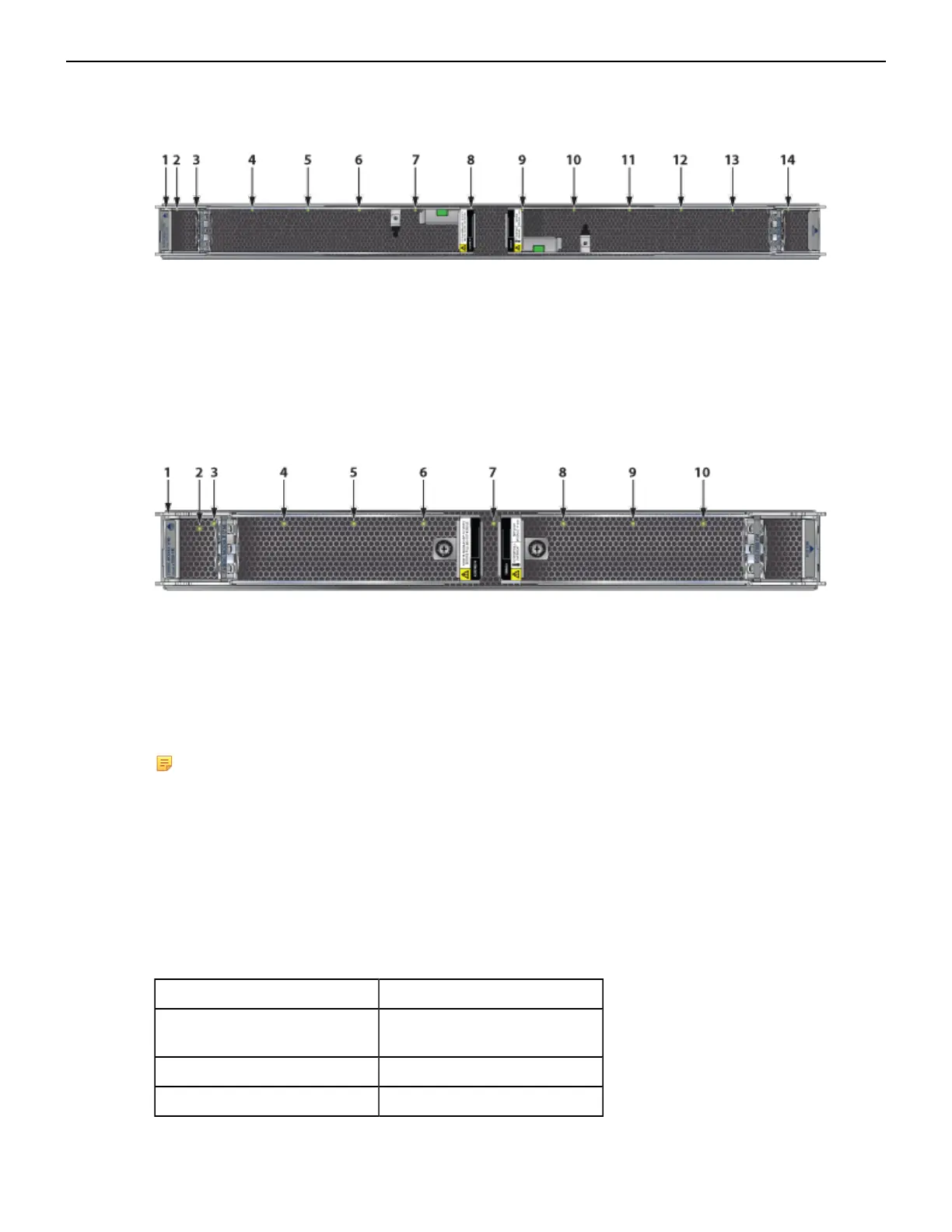
Figure 26: DCS-7812R3-FM Fabric Module
1 Fabric module top 6 Fan module 4 status LED 11 Fan module 8 status LED
2 Fabric module status LED 7 Fan module 5 status LED 12 Fan module 9 status LED
3 Fan module 1 status LED 8 Fan module 6 status LED 13 Fan module 10 status LED
4 Fan module 2 status LED 9 Fabric module ejector lever 14 Fan module 11 status LED
5 Fan module 3 status LED 10 Fan module 7 status LED
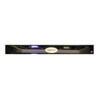
Figure 27: DCS-7808R3-FM and DCS-7816R3-FM Fabric Module and Fan Status LEDs
1 Fabric module top 5 Fan module 3 status LED 9 Fan module 7 status LED
2 Fabric module status LED 6 Fan module 4 status LED 10 Fan module 8 status LED
3 Fan module 1 status LED 7 Fan module 5 status LED
4 Fan module 2 status LED 8 Fan module 6 status LED
For the 7816 switch, the lower fabric module fan modules are numbered 9 through 16.
Note:
• DCS-7816R3-FM and DCS-7808R3-FM look similar. Check the label before populating the
chassis
• For the DCS-7816 switch, the top and bottom fabric modules form one logical fabric module.
Both physical modules in a logical pair power down if either loses power.
• The show module command lists the serial number (SN) of only the bottom-slot Fabric
Module.
Fan Status and Fabric Status LEDs on Rear Panel interprets the states of the fan and fabric status LED.
Table 13: Fan Status and Fabric Status LEDs on Rear Panel
LED State Status
Off Module inserted, but status is
unknown.
Green Module operating normally.
Red Module failed.
43