Cabling the Modular Switch
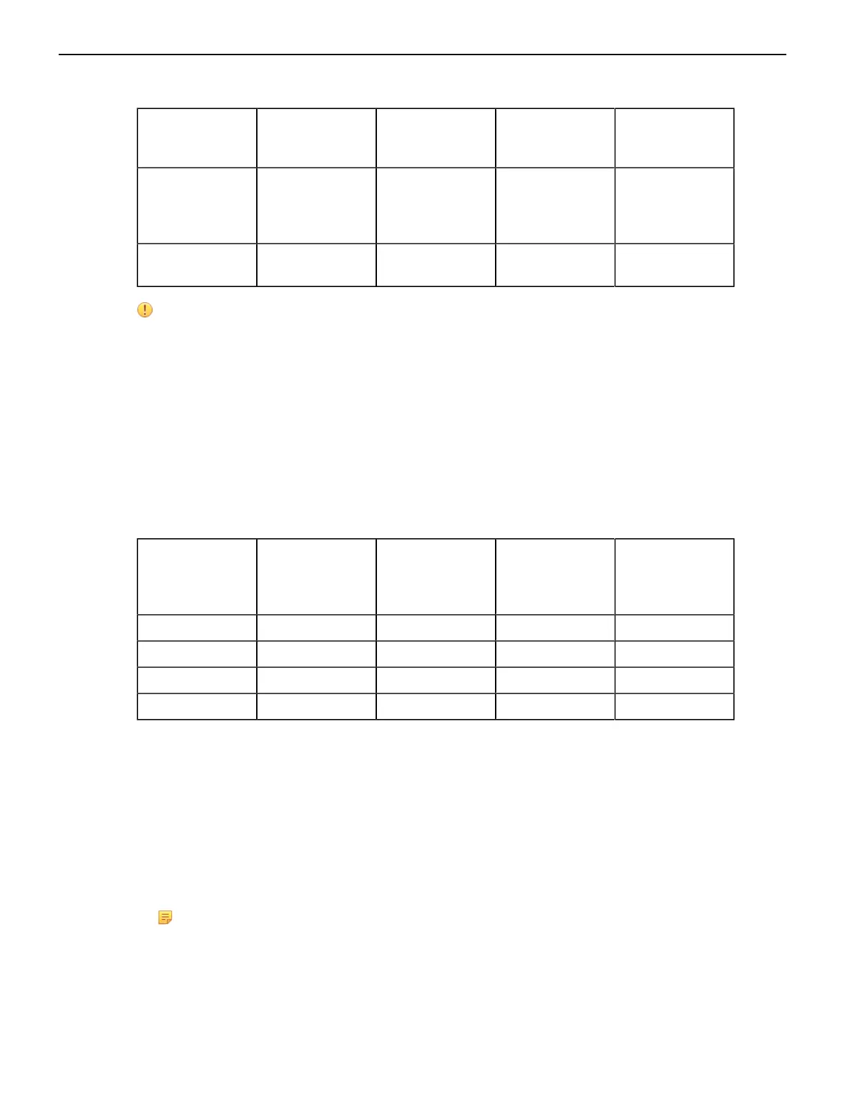
Table 8: Power Supply Specifications (each PSU)
Power Supply Maximum
Output Power
Rating (DC)
Input Voltage
and Frequency
Maximum Input
Current
Input Branch
Circuit
Protection
PWR-D1-3041-
AC-BLUE
3000 W 200 to 240
VAC(nominal)
50/60 Hz
(nominal)
2x 16 A 2x 20 A
PWR-D2-3041-
DC-BLUE
3000 W -48 V to -60 VDC,
70 A to 55A
2x 70 A 2x 90 A
Important: Each power supply requires input branch circuit protection in compliance with AHJ
requirements.
Chaque alimentation nécessite une protection du circuit de la branche d’entrée conformément
aux exigences de l’AHJ.
4.6 Power Supply Configurations
The Table 9: Power Supply Configurations shows the power supply configurations for the
modular switches.
Table 9: Power Supply Configurations
Modular Switch Recommended
Number of
PSUs (for
redundancy)
Number of PSUs
Shipped in
Bundle
Minimum
Number of PSUs
Required
Maximum
Number of PSUs
Supported
DCS-7804 6 6 6 8
DCS-7808 8 8 8 12
DCS-7812 10 10 10 18
DCS-7816 12 12 12 24
4.6.1 Recommendations for Power Supply Usage
• Use separate circuits (A & B) with required protection for each power supply.
• Use the same PSU model when replacing a failed PSU. Any suitable alternative must be approved
before using if the original model is no longer supported or available.
• Unless your switch allows for mixing power supplies, do not mix power supply types.
• To minimize distribution power loss, use an equal number of supplies in each row: (e.g 4 PSUs in
slots 1-4 and 4 PSUs in slots 7-10 for a configuration with 8 PSUs for the DCS-7808 switch). Table
7: Recommended PSU Bay Population Order provides more details.
Note: PSUs can be housed in either of two rows for the DCS-7808 switch. The LEDs for
PSUs in each row indicate correct status only after at least one of the PSUs in that row
(PSU1 to PSU6 or PSU7 to PSU12) is energized from a power source. For the DCS-7812 and
DCS-7816 switches, as long as one PSU is powered, all PSU LEDs will report status correctly.
31