Status Indicators
LED Name and State
Ethernet Port
Supervisor and System
Condition
(1)
Status Active Power
Supply
(PSU)
Line
Card
(LC)
Fabric
Module
(FM)
Fan
Module
Link
(Left)
Activity
(Right)
Supervisor active,
Ethernet port linked with
activity
Green Green (3) (3) (3) (3) Green Green
Supervisor active,
Ethernet port linked with
no activity
Green Green (3) (3) (3) (3) Green Off
Supervisor active,
Ethernet port not linked
Green Green (3) (3) (3) (3) Off Off
1
Assumes redundant supervisor is present.
2
Depends on port operation.
3
Green for normal operation, red if no corresponding component is powered or present.
Note: Arista modular switches take 15 to 30 minutes to boot completely.
A.2
Line Card Module Indicators
Each line card module provides one status LED plus LEDs for each port on the card. Line Card Status
LED shows a representative line card. The figures in Line Cards indicate the location of the LEDs on
each line card.
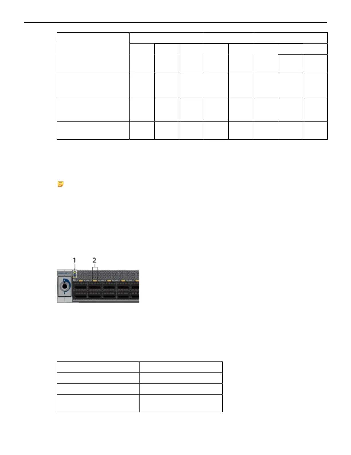
Figure 24: Line Card Status LED
1 Line card status LED
2 Port status LED
Line Card Status LED States interprets the states of the status LED.
Table 11: Line Card Status LED States
LED State Status
Off Line card not inserted.
Green Line card operating normally.
Yellow (amber/orange) Line card administratively shut
down or booting up.
41