Appendix C
Front Panel
This appendix displays the front panel of all switches covered by this guide.
Note: Depending on the components used to populate the chassis, the appearance of a
specific switch could be different.
Note: All switches are designed to fit in 19-inch racks.
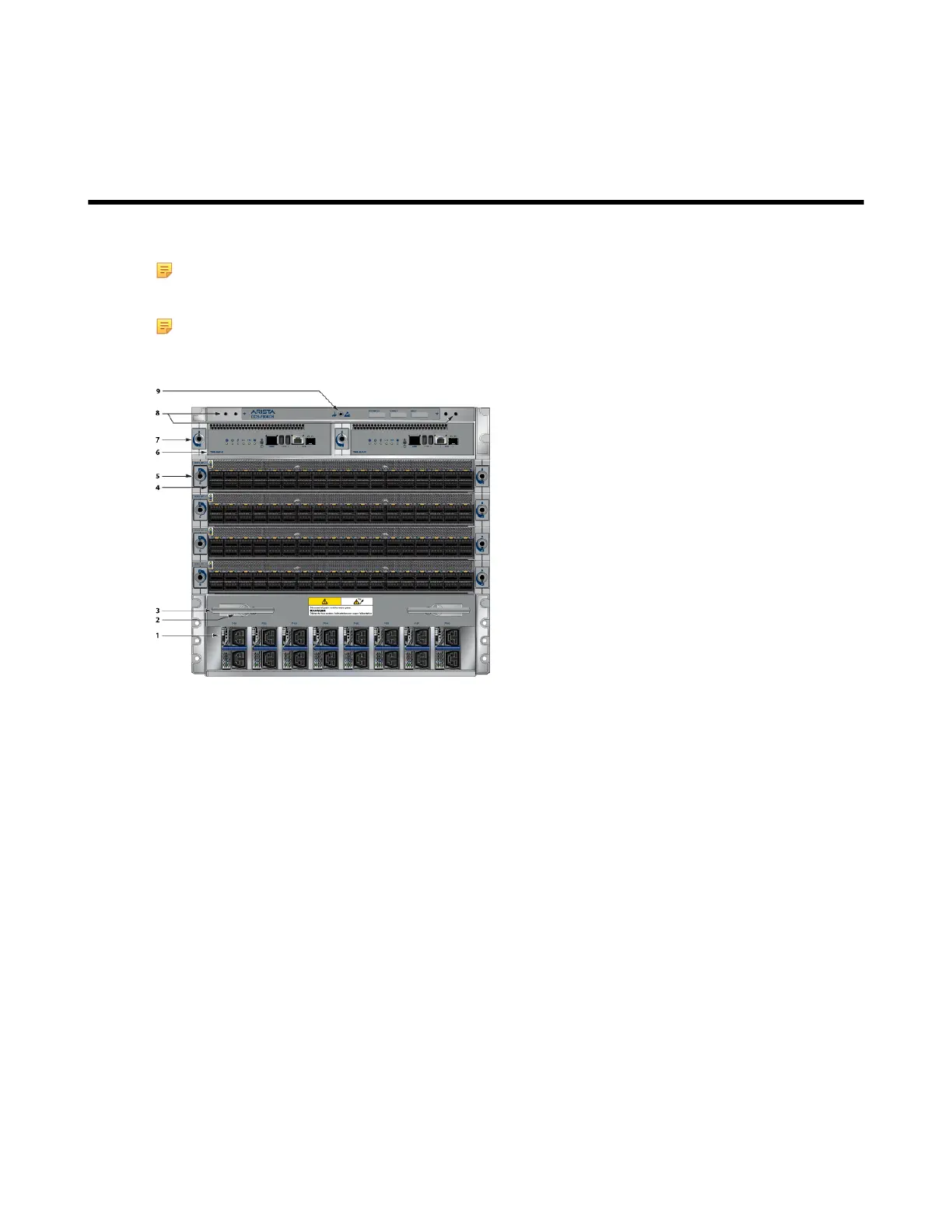
Figure 32: DCS-7804 Front Panel (Fully Populated)
1 Power supplies 4 Line cards 7 Supervisor lock
2 Line card and Supervisor
extraction tool tether
5 Line card lock 8 Grounding locations
3 Extraction tool 6 Supervisor modules 9 ESD attach point
51