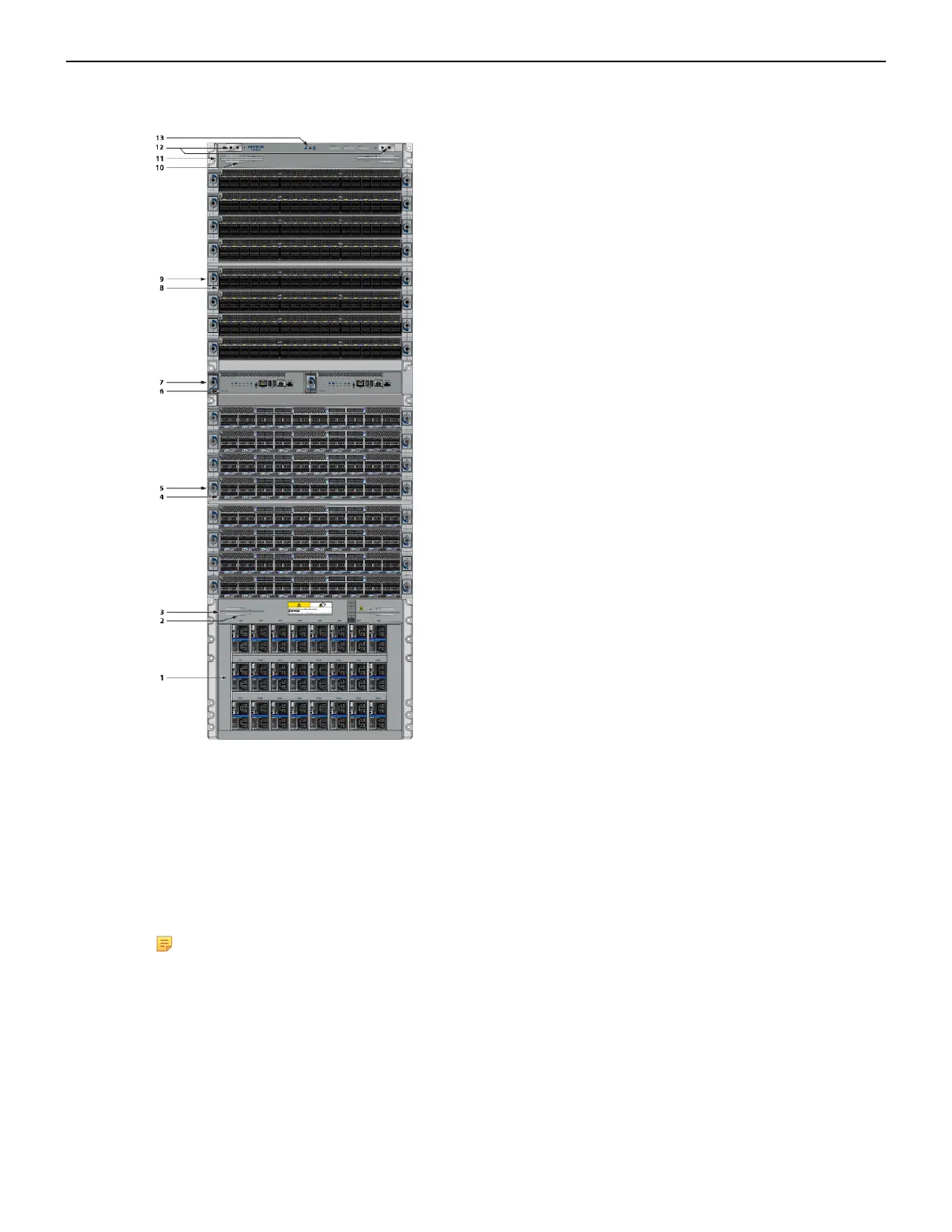
Figure 16: Front Panel (DCS-7816)
1 Power supplies 6 Supervisor modules 11 Extraction tool
2 Linecard and Supervisor
extraction tool tether
7 Supervisor lock 12 Grounding locations
3 Extraction tool 8 Linecards 13 ESD attach point
4 Linecards 9 Linecard lock
5 Linecard lock 10 Linecard and Supervisor
extraction tool tether
Note: To power down the switch, remove all power cords from the power inlets.
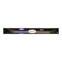
4.3 Cabling the AC Power Supplies
The switches use PWR-D1-3041-AC-BLUE (Figure 17: AC Power Supply) power supplies with SAF-
D-GRID connectors on the PSU inputs. Power cables are included with the accessory kit (Table 16:
Accessory Kits for the Modular Switches). To power the switch, insert the other side of the cable into
the main power providing circuit.
28