WARNING
Risk of injury or equipment damage
Connecting the Telephony Gateway to the home's existing telephone
wiring should only be performed by a professional installer. Physical con-
nections to the previous telephone provider must be removed and the
wiring must be checked; there must not be any voltage. Cancellation of
telephone service is not adequate. Failure to do so may result in loss of
service and/or permanent damage to the Telephony Gateway.
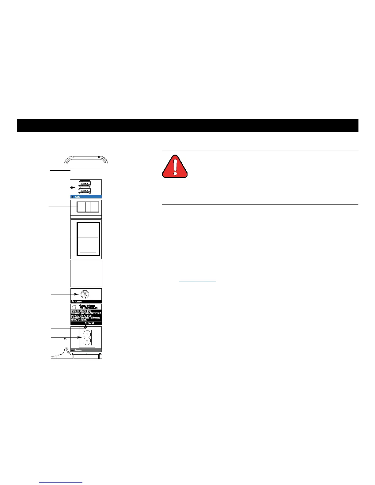
1 Connect one end of the coax cable to the cable outlet or splitter, and the other
end to the Telephony Gateway's Cable connector (F). Tighten the con-
nections by hand, then tighten an additional 1/8 turn with a wrench.
Note: For best performance, use high-quality coax cable and minimize or
eliminate splitters between the cable jack and the Telephony Gateway.
2 Insert the plug from the power cord into the Power connector on the back of
the Telephony Gateway (H) and insert the power cord into a convenient
AC outlet.
The Power light on the front of the Telephony Gateway lights up, then flashes
once (refer to the LED tables shown in Using the Telephony Gateway). See
Troubleshooting if the Power light does not turn on.
3 Connect one end of the Ethernet cable to any Ethernet port on the back of
the Telephony Gateway, (E) and the other end to the Ethernet port on a
computer, hub, or broadband router.
Note: If you are connecting to a computer or an Ethernet hub with a
crossover switch, use a straight-through cable.
4 Connect one end of the telephone cable to the telephone port on the back of
the Telephony Gateway (C or D). Connect the other end to the telephone.
Home Alarm Connection
If you are only using one phone, connect it to Tell (C), then connect your
home alarm to Alarm/Te12 (D).
If you are using two phones, connect the first phone and your home alarmto
Tell (C) using an RJ-31X jack. Connect the second phone to Alarm/Te12 (D).