5200 Series Programming Instructions
15
80-9352-0022-020 Rev 2 06/23
Copyright © 2023, ASSA ABLOY Accessories and Door Controls Group, Inc. All rights reserved. Reproduction in whole or in
part without the express written permission of ASSA ABLOY Accessories and Door Controls Group, Inc. is prohibited.
Single-Use Restroom Wiring Diagram (cont.)
Example 2: Push/Pull
Outside
Restroom
Switch
PUSH
TO
OPERATE
PUSH
TO
OPERATE
Inside
Restroom
Switch
C
NO
Latch Monitor
Hardware Components
y One (1) Deadbolt w/ privacy indicator
y One (1) Latch Monitor
y One (1) Push/Pull set
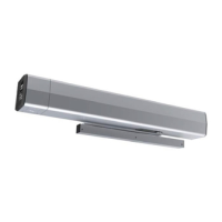
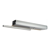
y One (1) 5200 Series Low Energy Operator
y Two (2) Activation switches
Description of Operation:
y Door normally closed and unlocked.
y Outside door switch activates operator.
y Projecting deadbolt disables inside and
outside door switch, changes occupancy
indicator status.
y Retracting deadbolt re-enables inside
door switch.
y Exiting room re-enables outside door
switch.
Input Configuration:
 Loading...