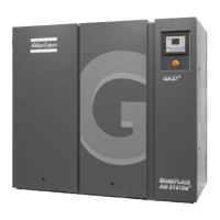
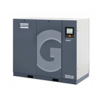
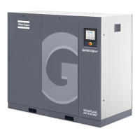
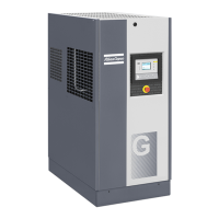
CSA/UL (cULus) cubicle
Step Action
1 Install an isolating switch near the compressor.
2 Check the fuses and the setting of overload relay. See section Settings of overload relay
and fuses.
3 If fitted, check transformers for connection.
4 Connect the power supply cables to terminals L1, L2 and L3 (1X0) and the neutral
conductor (if applicable) to terminal (N). Connect the earth conductor.
Specific instructions for GA 5 up to GA 11 with 208 V/ 230 V / 460 V cubicle
Always disconnect the power supply before working on the electrical circuit!
The standard voltage configuration for the compressor is mentioned on the data plate of the machine. When
the compressors leave the factory, the units are connected for 230 V / 3 phase.
Instruction book
2920 7090 51 127
 Loading...
