Compressed air circuit
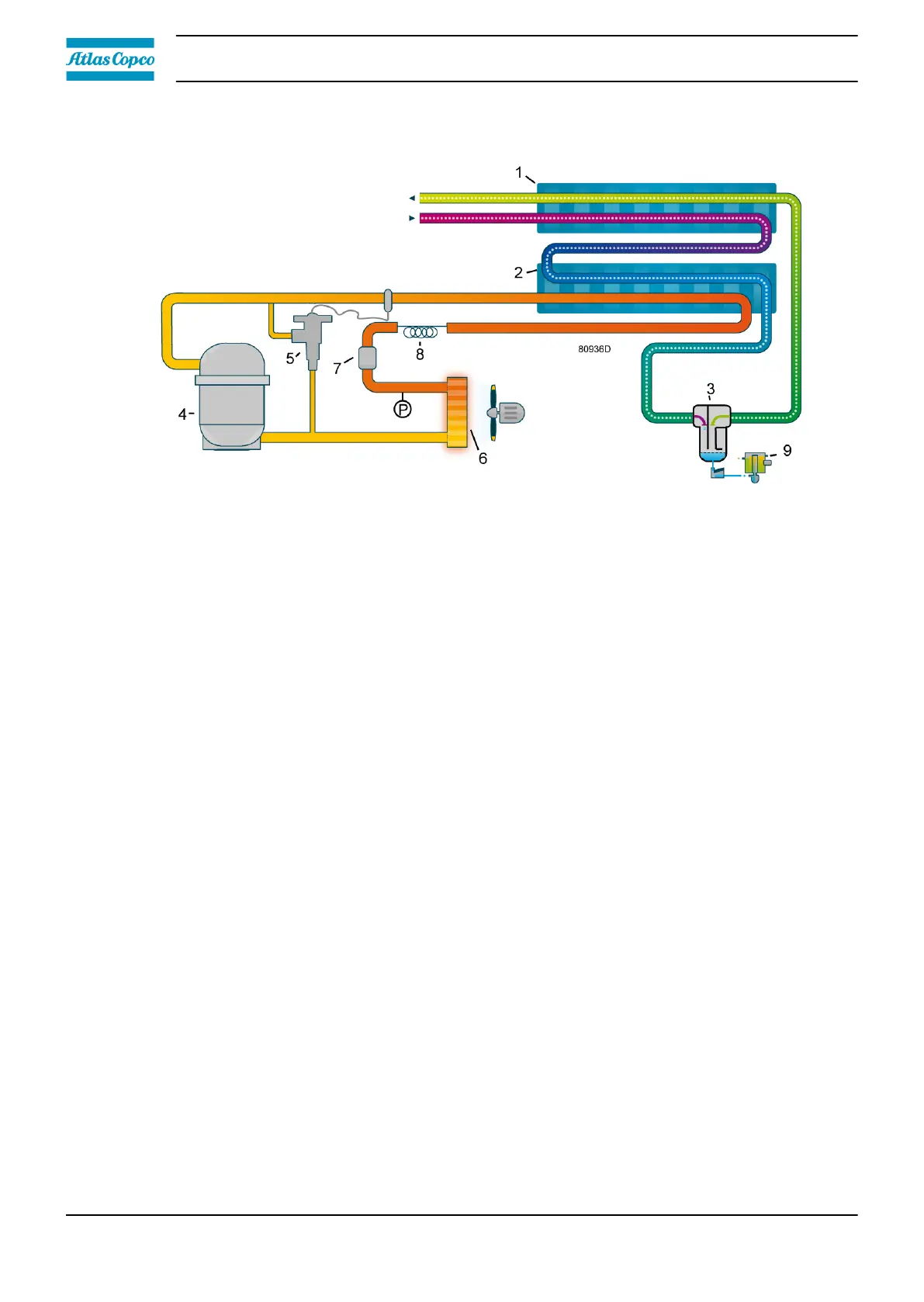
Compressed air enters the heat exchanger (1) and is cooled by the outgoing, cold, dried air. Water
in the incoming air starts to condense. The air then flows through the evaporator/heat exchanger (2)
where the refrigerant evaporates, causing the compressed air to be cooled further to close to the
evaporating temperature of the refrigerant. More water in the air condenses. The cold air then flows
through the water separator (3), where the condensate is separated from the air. The condensate is
automatically drained by the timer drain (9).
The cold, dried air flows through the heat exchanger (1) where it is warmed up by the incoming air.
Refrigerant circuit
The compressor (4) delivers hot, high-pressure refrigerant gas which flows through the condenser
(6) where most of the refrigerant condenses.
Next, the liquid refrigerant flows through the dryer/filter (7) to the capillary tube (8). The refrigerant
leaves the capillary tube at evaporating pressure.
The refrigerant enters the evaporator (2) where it withdraws heat from the compressed air by
further evaporation at constant pressure. The heated refrigerant leaves the evaporator and is
sucked in again by the compressor.
The condenser (6) pressure must be kept as constant as possible to obtain stable operation. The
fan control switch (P) therefore stops and starts the condenser cooling fan. If, under partial or no
load, the evaporator (2) pressure drops to approximately 2.25 bar(e) (32.63 psig), the hot gas
bypass valve (5) opens and hot, high-pressure gas is fed to the evaporator circuit to prevent the
evaporator pressure from dropping any further.
Instruction book
20 2920 7219 10