Operation
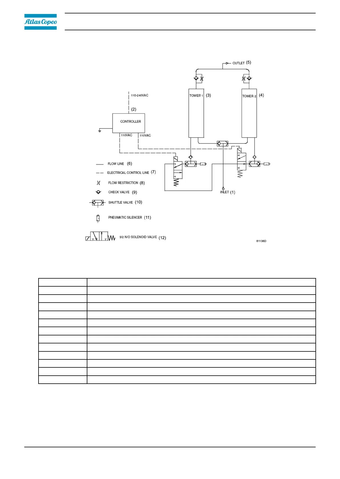
Figure 9: Flow diagram CD 3
+
Reference Description
1 Compressed air inlet
2 Dryer controller
3 Left desiccant tower
4 Right desiccant tower
5 Compressed air outlet
6 Flow line
7 Electrical control line
8 Flow restriction
9 Check valve
10 Selector valve
11 Pneumatic silencer
12 Solenoid valve
The operation cycle of the dryer is repetitive and is controlled by a factory set timer. While the
desiccant in one tower dries the compressed air, the desiccant in the second tower is being
regenerated. Regeneration of the desiccant is achieved by means of purge air from the drying
tower.
Instruction book
22 2920 7219 10