INSTALLATION and POWER
page 1 – 2
D-75 / Sep 2004
Installation and Power
Unpacking the Console
The D-75 console is shipped as two packages. One carton contains the
console and technical documentation; and the other contains the rackmount
power supply, connecting cable, and connector kit.
Countertop Mounting
The D-75 audio console is designed for countertop mounting. Console
placement should avoid proximity to any electromagnetic fields, such as
large power transformers, motors, and fluorescent lighting fixtures. If you
will be securing the console to the counter top, you may want to pre-drill
the mounting holes (see sketch below).
Set the console in place on the counter, and remove the screws that
hold down the first and the last modules in place (two per module).
Carefully remove those modules from the frame. Attach the console
mainframe to the counter top, using the holes provided in the bottom of
the chassis and screws appropriate to the counter material, and reinstall
the removed modules.
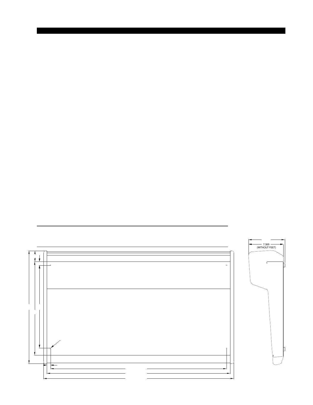
The console extends approximately 7 5/8” above the countertop at the
meterbridge. The hinged meterbridge will require 14” above the countertop
surface and 4 3/4” behind the rear meterbridge to open freely.
Do not connect the D-75 console to its power supply (and do not
connect the power supply to the AC power line) until instructed to do
so.
NOTE: This console
contains static-sensitive
devices. Normal pre-
cautions against static
discharge should be ob-
served when handling
individual modules.
NOTE: Dimensions shown are for 26 position
mainframes; 18 position frames dimensions
shown in ()
40.770 (28.690)
24.180
37.750 (25.670)
17.750
39.270 (27.190)
.760
7.369
(WITHOUT FEET)
7.6341
D = .171"; USE #8
SCREWS
2.356
20.044
.75
7.369
(WITHOUT FEET
7.6341
D = .171”; USE #8 SCREWS