page 3 – 4
D-75 / Sep 2004
STEREO LINE INPUT
details). As long as this closure is maintained (i.e., as long as talent holds down
the studio TB button) the module’s (pre-fader, pre-on/off) signal will be placed
on the console’s Cue bus.
Attenuation
As mentioned in the Read Me! pages at the front of the manual, there is
a tendency today for CD’s to be made with less than 1dB of headroom. Any
boosting of level resulting from moving the fader up from the nominal, unity
gain, position results in overload distortion. For this reason, dipswitch position
2 is provided to attenuate a channel’s signal by 12dB, thus allowing channels
being fed by such hot CD’s to have their faders moved above nominal without
causing distortion. The 12dB attenuation is applied to the four main stereo buses,
cue, and talkback — in other words, anywhere in the console that the channel’s
audio may be routed.
SW1 position 2 applies 12dB of attenuation to the channel for all bus feeds
EFS - European Fader Start
In some situations it is desirable to have the channel’s on/off status controlled
by the position of the fader. In such a scenario, if the fader is all the way down
and the channel is off, moving the fader up slightly from the full down position
will turn the channel on without the need to press the channel ON button. In a
similar manner, if the fader is up from the full down position by at least a small
amount and the channel is on, moving the fader to the full down position will turn
the channel off without the need to press the channel OFF button. This feature
is enabled by moving the dipswitch position 1 to the right (on).
SW1 position 1 enables the EFS feature
Hook-Ups
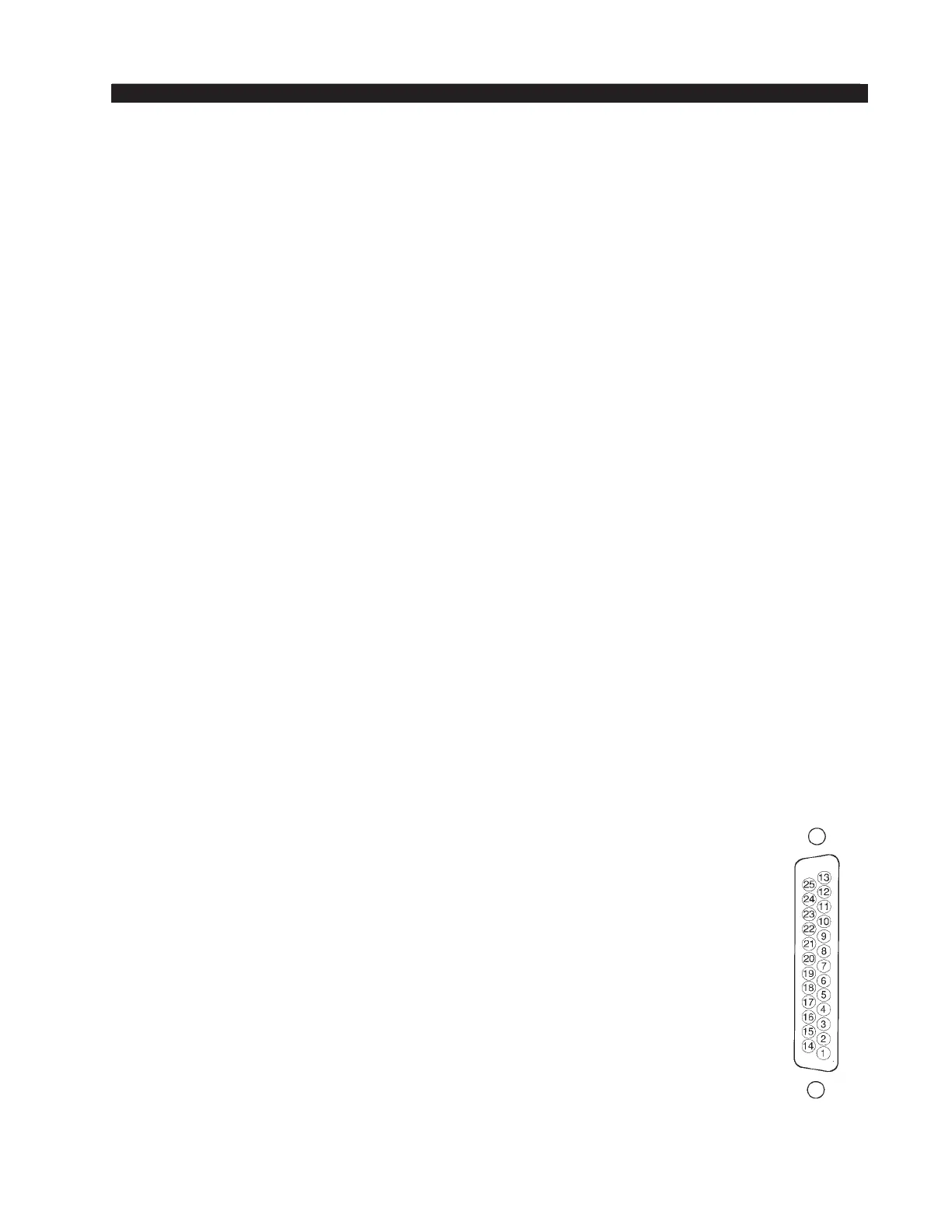
As stated before, all user wiring to and from IN-75 modules takes place at
the DB-25 multi-pin connector mounted on the daughter card at the top of each
module. There is one connector per module. Pinout drawings on pages 3-7 and
3-8 show all wiring connections at a glance.
Audio Connections — Analog Inputs (ADC-75)
These include A and B source inputs; level is +4dBu balanced.
Pin 25 – Line A Lt In SH
Pin 24 – Line A Lt In HI
Pin 12 – Line A Lt In LO
Pin 11 – Line A Rt In SH
Pin 10 – Line A Rt In HI
Pin 23 – Line A Rt In LO
Pin 22 – Line B Lt In SH
Pin 21 – Line B Lt In HI
Pin 9 – Line B Lt In LO
Pin 8 – Line B Rt In SH
Pin 7 – Line B Rt In HI
Pin 20 – Line B Rt In LO
D-75 / Jan 2014
Typical DB-25
connector
NOTE: If you are bringing a
mono signal into the IN-75
and want it to go to both left
and right sides of the stereo
busses, simply bridge the left
and right sides of the input
together when wiring.