page 7 – 5
D-75 / Sep 2004
SUPERPHONE INPUT
Hook-Ups
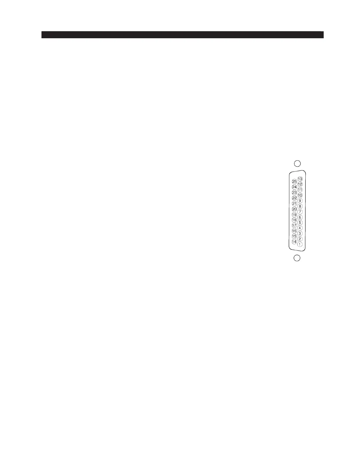
As stated before, all user wiring to and from the SP-75 modules takes
place at two multi-pin DB-25 connectors mounted on the top of the module.
Typical DB-25
connector
D-76 / June 2015
Left DB-25 “B” Connector — Audio and Control
Handles module’s Composite, Mics, Callers, Hybrid 1, and Hybrid 2 audio
outputs, and the remote start and stop outputs. All audio signals are analog
mono.
Pin 25 – Composite Out SH
Pin 24 – Composite Out HI
Pin 12 – Composite Out LO
Pin 11 – Mics Out SH
Pin 10 – Mics Out HI
Pin 23 – Mics Out LO
Pin 22 – Callers Out SH
Pin 21 – Callers Out HI
Pin 9 – Callers Out LO
Pin 8 – Hybrid 1 Out SH
Pin 7 – Hybrid 1 Out HI
Pin 20 – Hybrid 1 Out LO
Pin 19 – Hybrid 2 Out SH
Pin 18 – Hybrid 2 Out HI
Pin 6 – Hybrid 2 Out LO
Pin 5 – N/C
Pin 4 – Start/Stop Com
Pin 17 – Start/Stop Com
Pin 16 – Stop
Pin 15 – Start
Pin 3 – Stop
Pin 2 – Start
Pin 1 – N/C
Pin 14 – N/C
To START and STOP Remote Source Machines Using Module ON/OFF
Switches
EXTERNAL START — Hook up the remote machine’s Start control pins
to the SP-75 module’s DB-25 connector control pins: for START wire to
pins 2 (15) and 4 (17).
EXTERNAL STOP — Hook up the remote machine’s Stop control pins
to the SP-75 module’s DB-25 connector control pins: for STOP wire to pins
3 (16) and 4 (17).