page 7 – 6
D-75 / Sep 2004
SUPERPHONE INPUT
When the module’s ON/START switch is pressed, an opto-isolated
closure takes place between START/STOP COMMON and START;
when the module’s OFF switch is pressed, an opto-isolated closure takes
place between START/STOP COMMON and STOP. These may be used
to control a remote tape machine for recording phone segments.
Note, there are not two independent START and STOP outputs. There
are just two connections provided for each signal. Internally, pins 4 and 17
are connected together, pins 2 and 15 are connected together, and pins 3
and 16 are connected together.
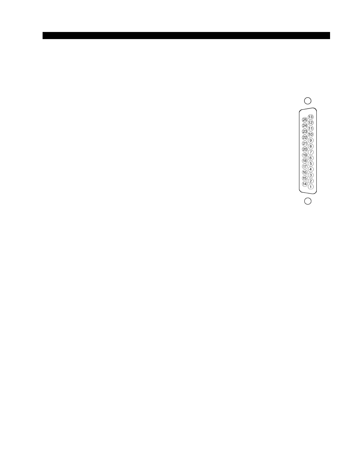
Right DB-25 “A” Connector — Audio
Handles module’s mono External and Hybrid inputs. All audio signals
are analog stereo, +4dBu balanced.
Pin 25 – Ext In SH
Pin 24 – Ext In HI
Pin 12 – Ext In LO
Pin 22 – Caller 1 In SH
Pin 21 – Caller 1 In HI
Pin 9 – Caller 1 In LO
Pin 8 – Caller 2 In SH
Pin 7 – Caller 2 In HI
Pin 20 – Caller 2 In LO
Typical DB-25
connector