page 3 – 2
D-75 / Sep 2004
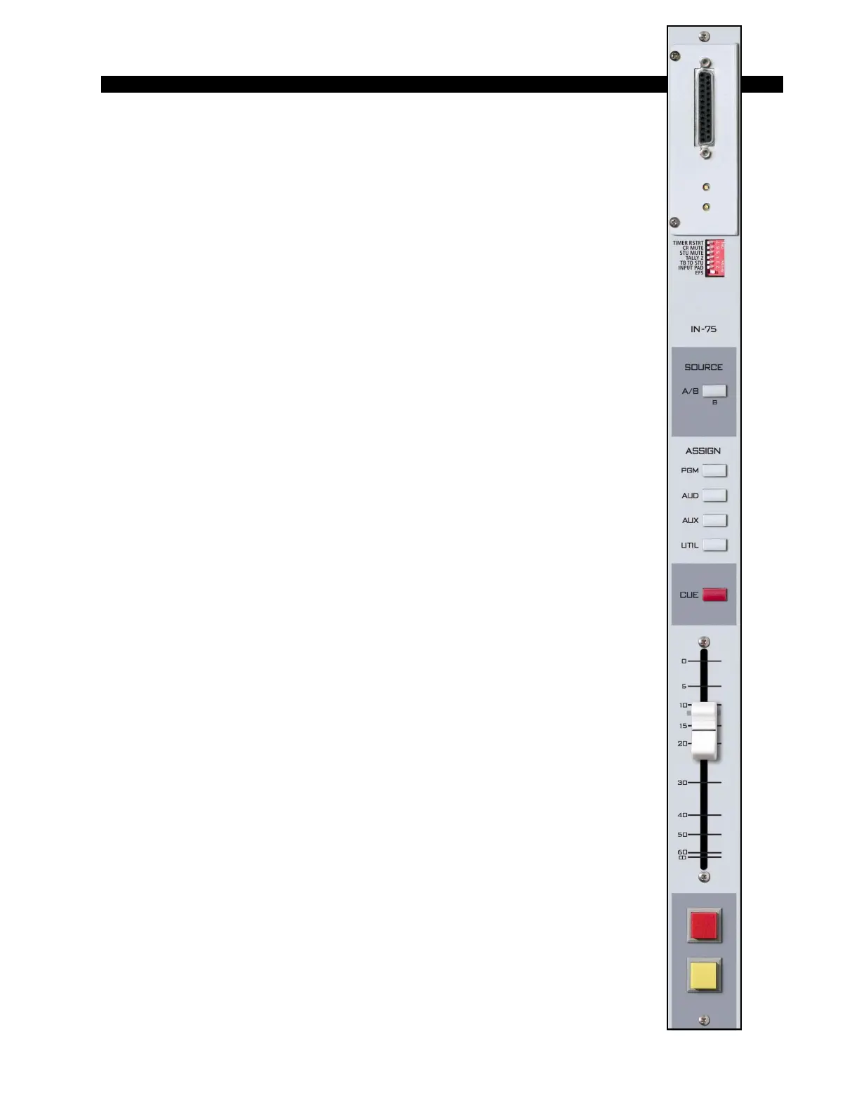
STEREO LINE INPUT
Stereo Line Input
(IN-75)
Module Overview
IN-75 modules are for mic inputs signals (from the QMP-4) and stereo
line input signals.
At the top of the module, underneath the hinged meterbridge, is a plug-
in daughter card that determines if the module is a digital input (SRC-75)
or an analog input (ADC-75). If the module is being used to handle mic
signals from the QMP-4, it will need to have the ADC-75 daughter card.
The ADC (analog-to-digital converter) version accepts +4dBu bal-
anced analog input signals. PCB-mounted multi-turn trimpots adjust the
left and right levels.
The SRC (sample rate converter) version accepts digital (AES is
factory default) input signals.
Each module accepts two stereo sources, A and B, switched at the top
of the module. Output switches assign the selected source signal to any
combination of the console’s four stereo outputs—PGM (program),
AUD (audition), AUX (auxiliary), and UTIL (utility). Please note, the
UTIL bus is pre-fade, pre-on. This feature can be defeated (see
page 10-4).
A CUE switch places the module’s signal on the console’s cue bus,
where it may be heard on the meterbridge mounted cue speaker and/or as
an interrupt to the console operator’s headphones and/or control room
monitor speakers. The various cue interrupt modes are programmed at the
console’s CR-75 (Control Room) module via PCB-mounted dipswitch.
See page 5-3.
Level is set by a long-throw fader.
Channel ON (START) and OFF (STOP) switches are at the bottom of
the module. In addition to being controlled remotely, these can also be
programmed (via internal PCB-mounted dipswitch) to perform a variety
of functions, including starting and stopping external source machines,
activating control room and studio mutes, external tallies, and timer
restart. The STOP switch’s LED can be controlled by an external source
machine to act as a “ready” indicator.
All audio and control input and output signals are made via the multi-
pin DB-25 connector mounted on the top of the module and located
underneath the hinged meterbridge.
D-75 / Feb 2005