INSTALLATION and POWER
page 1 – 3
D-75 / Sep 2004
CONSOLE
2-TRACK
MULTI-TRACK
AC BREAKER
BOX
DEVICE 1
DEVICE 2
DEVICE N
CONSOLE POWER SUPPLY
CONTROL ROOM POWER AMP
STUDIO POWER AMP
OTHER
POWER COMPANY
EARTH GROUND
HEAVY
(#4 or #6)
COPPER
WIRE
HIGH POWER
EQUIPMENT RACK
COPPER ROD
SOIL
3-wire ground or separate wire run from chassis
EFFECTS RACK
MIC PANEL
GND
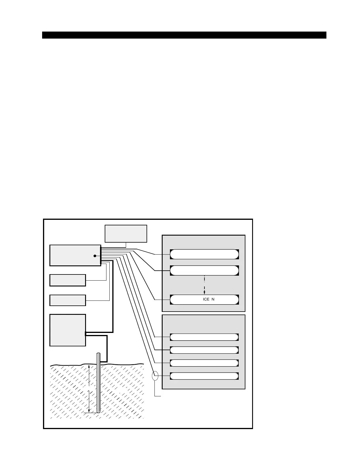
TYPICAL SYSTEM
GROUNDING SCHEME
etc.
3–5 ft.
Tie the console ground lug
terminal strip to the system
earth ground. Tie every piece
of equipment in the entire
audio system to the console
ground lug terminal strip.
System Ground
The first step is to ground the console.
Note that as supplied from the factory, console rackmount power
supply common, audio ground, and the D-75 mainframe are connected
together at the console, but are NOT connected to electrical ground and
the chassis of the power supply. Safety requirements dictate that a
positive connection from the console mainframe to electrical ground be
made in the completed installation. Use the grounding lug on the rear
of the mainframe to establish your system ground. The grounding lug
may be found at the rear of the console, on the rear frame panel, to the
left if you are looking at the rear of the console.
The system ground serves two important purposes:
(1) It provides a zero signal reference point for the entire audio system;
(2) It assures safety from electrical shock.
There exist two terms that one encounters in a discussion of ground:
(A) EARTH GROUND, which is usually a heavy copper rod driven into the
soil adjacent to the building (around 6 feet down) or a connection to the copper
water pipes leading into the building. Either is acceptable (unless, of course,
the water pipe is made of plastic).