page 4 – 4
D-75 /Sep 2004
OUTPUT MODULE
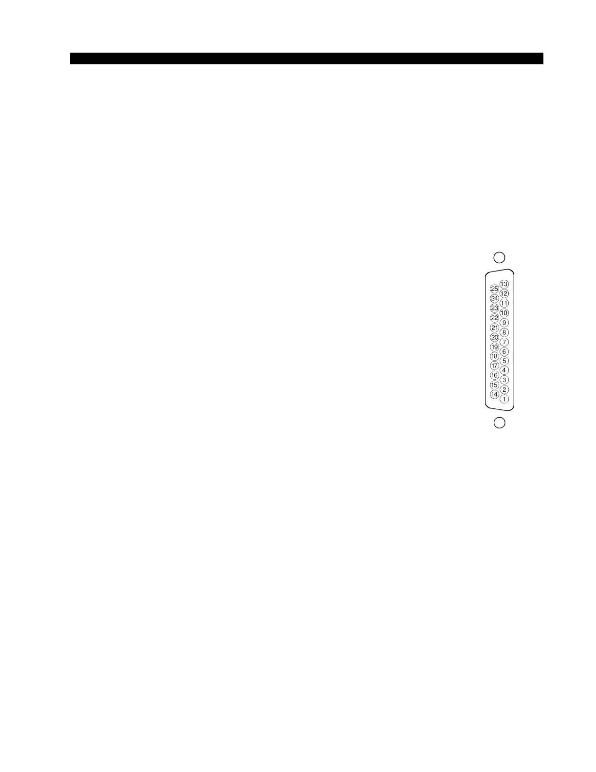
Typical DB-25
connector
Hook-Ups
As stated before, all user wiring to and from the OM-75 module takes place
at two DB-25 multi-pin connectors at the top of module.
Left DB-25 “B” Connector – Digital Audio Outputs
and External Analog Inputs
Handles External inputs and Program, Audition, Auxiliary, and Utility digital
outputs. The external analog input signals are +4dBu balanced.
Pin 25 – PGM AES Out SH
Pin 24 – PGM AES Out HI
Pin 12 – PGM AES Out LO
Pin 11 – AUD AES Out SH
Pin 10 – AUD AES Out HI
Pin 23 – AUD AES Out LO
Pin 22 – AUX AES Out SH
Pin 21 – AUX AES Out HI
Pin 9 – AUX AES Out LO
Pin 8 – UTIL AES Out SH
Pin 7 – UTIL AES Out HI
Pin 20 – UTIL AES Out LO
Pin 19 – Ext 1 Lt In SH
Pin 18 – Ext 1 Lt In HI
Pin 6 – Ext 1 Lt In LO
Pin 5 – Ext 1 Rt In SH
Pin 4 – Ext 1 Rt In HI
Pin 17 – Ext 1 Rt In LO
Pin 16 – Ext 2 Lt In SH
Pin 15 – Ext 2 Lt In HI
Pin 3 – Ext 2 Lt In LO
Pin 2 – Ext 2 Rt In SH
Pin 1 – Ext 2 Rt In HI
Pin 14 – Ext 2 Rt In LO
Right DB-25 “A” Connector – Analog Audio Outputs
Handles Program, Audition, Auxiliary, and Utility analog outputs.
All signals are +4dBu balanced.
Pin 25 – PGM Lt Out SH
Pin 24 – PGM Lt Out HI
Pin 12 – PGM Lt Out LO
Pin 11 – PGM Rt Out SH
Pin 10 – PGM Rt Out HI
Pin 23 – PGM Rt Out LO
Pin 22 – AUD Lt Out SH
Pin 21 – AUD Lt Out HI
Pin 9 – AUD Lt Out LO