page 2 – 3
D-75 / Sep 2004
Q U A D M I C P R E A M P
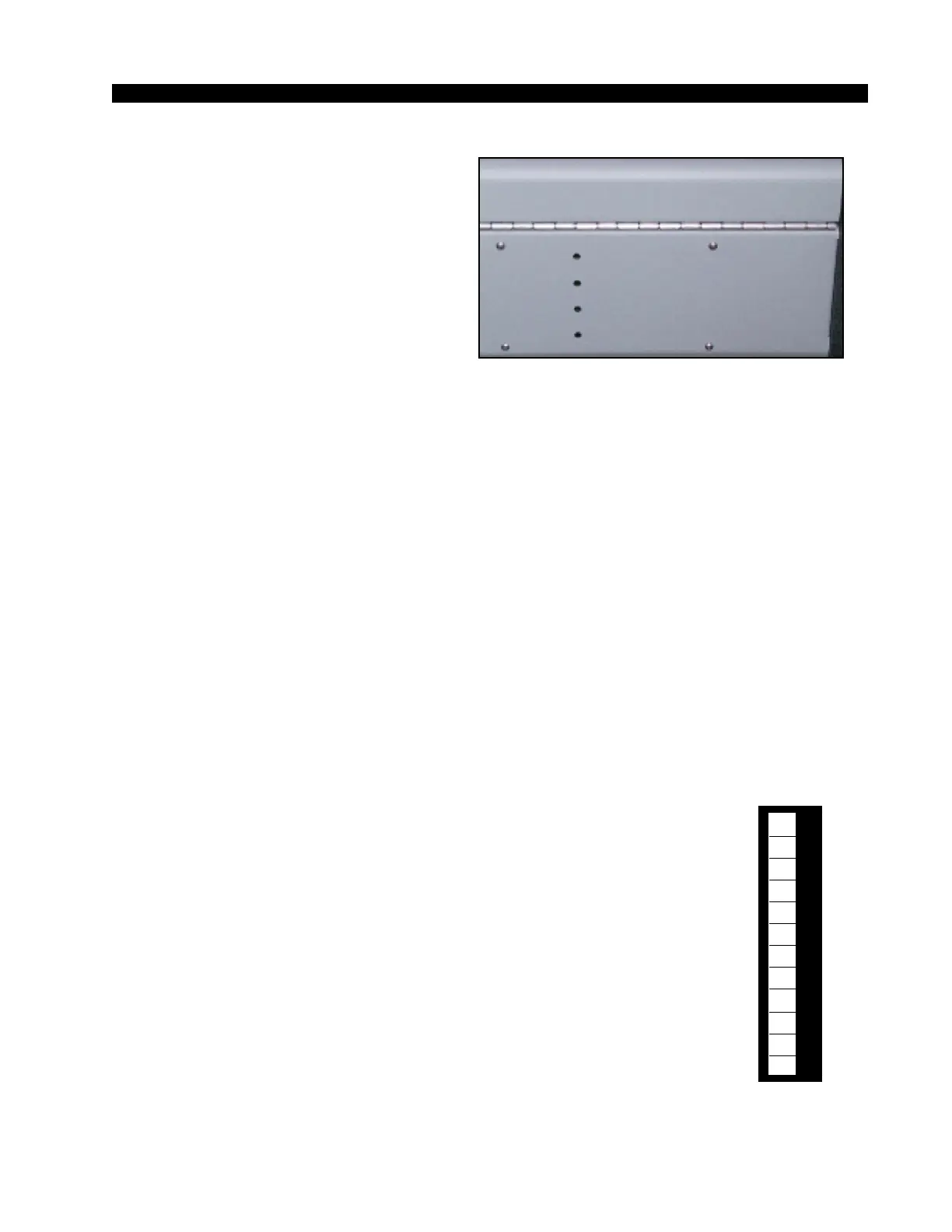
Recessed meterbridge rear trimpots
(range 38dB) adjust the level of each input
independently.
Example: with a microphone input of
–60dBm @150Ω at the port, gain trim can set
levels from -22dBu to +16dBu (note maximum
preamp gain is +76dB).
All audio input and output signals are made via two 12-position plug
terminals mounted on the QMP-4 PCB.
Internal Programming Options
Internal programming for the quad mic preamp is made via printed
circuit board (PCB) mounted seven-position dipswitch SW1. Note that
when a dipswitch position is thrown to the right it is ON.
Phantom Power
Dipswitch SW1 turns phantom power on for the four microphone input
ports.
SW1 position 7 activates phantom power for microphone 1
SW1 position 5 activates phantom power for microphone 2
SW1 position 3 activates phantom power for microphone 3
SW1 position 1 activates phantom power for microphone 4
Hook-Ups
As stated before, all user wiring to and from the QMP-4 takes place at
the 12-position plug terminals mounted on the QMP-4 PCB. A pinout
drawing on page 2-6 shows all wiring connections at a glance.
Audio Input Connections (CT3)
All signals are analog mono. The mic input level is normally -50dBu,
balanced.
Pin 1 – Mic 1 In SH
Pin 2 – Mic 1 In LO
Pin 3 – Mic 1 In HI
Pin 4 – Mic 2 In SH
Pin 5 – Mic 2 In LO
Pin 6 – Mic 2 In HI
Note the factory default
setting for phantom power
is OFF.
Mic 1
Mic 2
Mic 3
Mic 4
1
2
3
4
5
6
7
8
9
10
11
12
Typical 12-position
plug terminal
D-75 / Aug 2006