page 10 – 4
METERBRIDGE
D-75 / Sep 2004
External Sync
The clock can be synchronized to an external 1Hz signal (input on pin 1
of CT8, referenced to digital common at pin 2 of CT8) or an external 60Hz
signal (input on pin 1 of CT9, referenced to digital common at pin 2 of CT9).
SW1 position 2 enables synchronization to the 1Hz input
SW1 position 3 enables synchronization to the 60Hz input
Additionally, the clock can be synchronized from an ESE master generat-
ing TC-89 time code, brought in on pin 1 of CT10 and referenced to digital
common at pin 2 of CT10.
Dim
The timer and clock displays can be dimmed for operation in areas with
low ambient lighting.
SW1 position 4 enables clock and timer display dimming
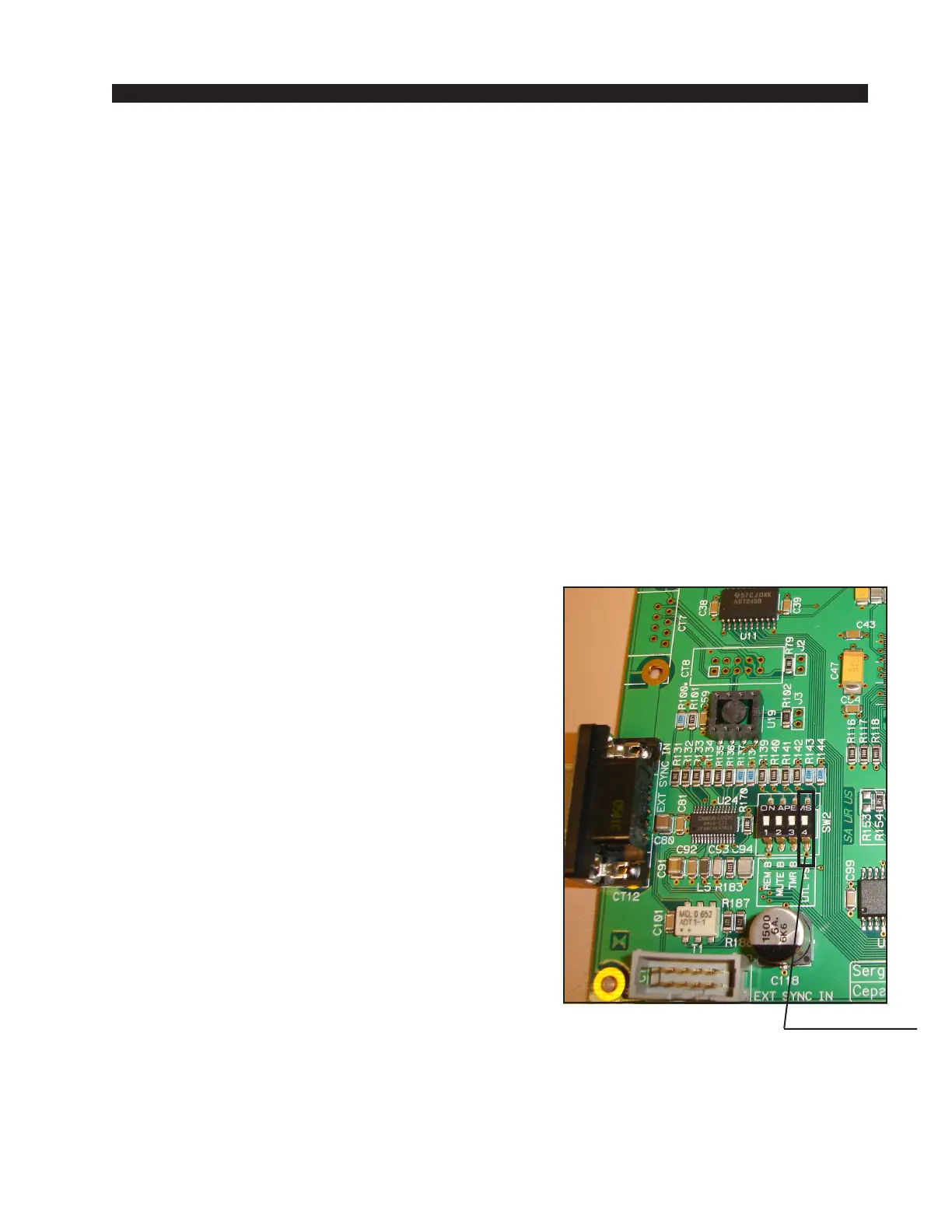
UTIL Pre-Fade / Pre-On Defeat
As shipped from the factory, D-75 input modules feed the UTIL bus pre-
fade, pre-on. This feature can be defeated for all input modules via position
4 of dipswitch SW2 on the PR-75 circuit board, located
in the meterbridge area, using the following procedure:
1. power down the console
2. open the meterbridge to provide access to PR-75
board
3. remove the 8 screws that hold the clear plexiglass
cover over the PR-75 board
4. do one of the following (4a or 4b):
4a. if the dipswitch is loaded on the board, throw
position 4 to the ON position, OR
4b. if there is no dipswitch present, solder a jumper
across the two position 4 pads (see photo).
5. replace the cover over the PR-75 board
6. close the meterbridge
7. power up the console
Please note, it is not possible to have some inputs
feed UTIL pre-fade and pre-on and have other inputs
feed UTIL post-fade and post-on. With SW2 position 4
open all inputs feed UTIL pre-fade, pre-on, and with
SW2 position 4 closed all inputs feed UTIL post-fade,
post-on.
D-75 / Sep 2007
position 4 pads