page 4 – 2
D-75 /Sep 2004
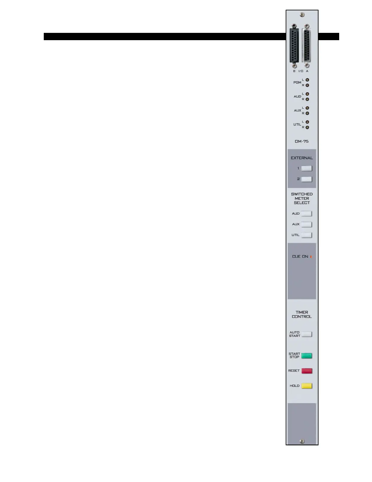
OUTPUT MODULE
Output Module
(OM-75)
Module Overview
The master output module handles the console’s Program, Audi-
tion, Auxiliary, and Utility outputs. All analog outputs are calibrated
with recessed front panel multi-turn trimpots.
The D-75 console has two pairs of left-right VU meters, PGM and
SWT (switched), located on the console’s meterbridge. The switched
meter follows the SELECT switching, allowing the console operator to
meter AUD, AUX and UTIL, and two external stereo line signals
(analog, +4dBu balanced), which may be brought into the module on
its DB-25 connector.
The OM-75 also has a master CUE ON indicator. Whenever any
input module is placed in cue the CUE ON indicator lights. At the same
time the switched meter pair automatically switches to show the level
of audio on the cue bus. While the CUE ON indicator is lit, the selected
switched meter source switch light goes off.
At the bottom of module are the timer control buttons (the timer
display is mounted in the righthand end of the console meterbridge):
AUTO START – enables timer restart functions from programmed input
modules’ ON buttons.
START/STOP - halts the timer, holds the last count, and then restarts and
accumulates the count when depressed again.
RESET - return to zero (if the timer is stopped it will hold at zero; if it is
running it will reset to zero and immediately begin counting up).
HOLD – when held down freezes the timer display (the counter keeps on
going); when released the display catches up to the current count.
All user wiring to and from the OM-75 module takes place at the
two DB-25 multi-pin connectors mounted on top of the module and
located underneath the hinged meterbridge. All analog audio is +4dBu
balanced. Pinout drawing on page 4-6 shows all wiring connections at
a glance.