Hardware Installation Manual 4 Document #: LTRT-10453
Mediant 500L MSBR
List of Figures
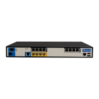
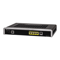
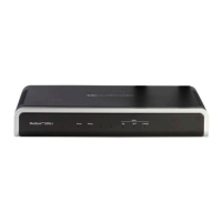
Figure 3-1: Front Panel .......................................................................................................................... 12
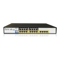
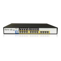
Figure 3-2: Rear Panel........................................................................................................................... 16
Figure 4-1: Minimum Vertical Space for 19-inch Rack Mounting .......................................................... 20
Figure 4-2: Positioning Shelf in Rack ..................................................................................................... 21
Figure 4-3: Positioning the Device's Anti-Slide Rubber Legs into Shelf's Openings ............................. 22
Figure 4-4: Device Mounted on Shelf in 19-inch Rack .......................................................................... 22
Figure 4-5: Dimensions for Drilled Holes ............................................................................................... 23
Figure 4-6: Protruded Screw Distance from Wall Surface ..................................................................... 25
Figure 4-7: Hanging Device on Screw Heads ....................................................................................... 25
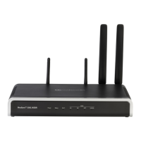
Figure 5-1: Orienting Wi-Fi Antenna ...................................................................................................... 26
Figure 6-1: Cabling the WAN Copper GbE Port .................................................................................... 29
Figure 6-2: Removing Protective Dust Plug........................................................................................... 30
Figure 6-3: Cabling the Fiber-Optic WAN GbE Port .............................................................................. 30
Figure 6-4: Cabling the xDSL WAN Port ............................................................................................... 32
Figure 6-5: Plugging the Cellular Modem into the USB Port (Example) ................................................ 33
Figure 6-6: Inserting SIM Card into SIM Slot ......................................................................................... 35
Figure 6-7: Connecting Cellular Antennas ............................................................................................. 36
Figure 6-8: Cabling LAN Ports ............................................................................................................... 38
Figure 6-9: RJ-45 Connector Pinouts for BRI Ports .............................................................................. 39
Figure 6-10: Cabling BRI Ports .............................................................................................................. 40
Figure 6-11: Cabling BRI PSTN Fallback .............................................................................................. 41
Figure 6-12: RJ-11 Connector Pinouts for FXS Interfaces .................................................................... 42
Figure 6-13: Cabling FXS Interfaces ..................................................................................................... 43
Figure 6-14: RJ-11 Connector Pinouts for FXO Interface ..................................................................... 44
Figure 6-15: Cabling FXO Interfaces ..................................................................................................... 44
Figure 6-16: Cabling the FXS Analog Lifeline ....................................................................................... 45
Figure 6-17: RS-232 Cable Adapter ...................................................................................................... 46
Figure 6-18: Cabling Serial Port ............................................................................................................ 46
Figure 6-19: Connecting USB Storage Device ...................................................................................... 47
Figure 6-20: 3A AC/DC Power Adapter ................................................................................................. 49
Figure 6-21: Inserting Plug into Power Adapter ..................................................................................... 50
Figure 6-22: Cabling to Power with 3A AC/DC Power Adapter ............................................................. 50
Figure 6-23: Cabling to Power with 5A AC/DC Power Adapter ............................................................. 51
List of Tables
Table 3-1: Physical Dimensions and Operating Environment ............................................................... 12
Table 3-2: Front Panel Description ........................................................................................................ 13
Table 3-3: Power LED Description ........................................................................................................ 13
Table 3-4: Status LED Description ........................................................................................................ 14
Table 3-5: Wi-Fi LED Description .......................................................................................................... 14
Table 3-6: WAN 4G LED Description .................................................................................................... 14
Table 3-7: WAN GE LED Description .................................................................................................... 15
Table 3-8: WAN SFP LED Description .................................................................................................. 15
Table 3-9: WAN A/VDSL LED Description ............................................................................................ 15
Table 3-10: Rear Panel Description ....................................................................................................... 16
Table 3-11: LAN LED Description .......................................................................................................... 18
Table 6-1: RJ-45 Connector Pinouts for Copper GbE WAN.................................................................. 28
Table 6-2: RJ-11 Connector Pinouts for xDSL ...................................................................................... 31
Table 6-3: LTE Variant Types ................................................................................................................ 34
Table 6-4: RJ-45 Connector Pinouts for GE .......................................................................................... 37
Table 6-5: RJ-45 to DB-9 Serial Cable Connector Pinouts ................................................................... 46
Table 6-6: Power Specifications ............................................................................................................ 48
Table 6-7: Power Adapter with Interchangeable Plugs ......................................................................... 49
Table A-1: Approved SFP Modules ....................................................................................................... 52
 Loading...