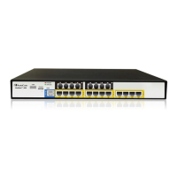
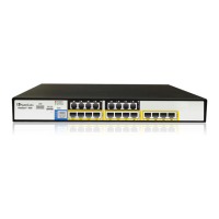
MSBR Series 35 Mediant 500 MSBR
Hardware Installation Manual 5. Cabling the Device
Pin Signal Name
4
Ethernet signal pair
5
7
Ethernet signal pair
8
Shield Chassis ground
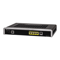
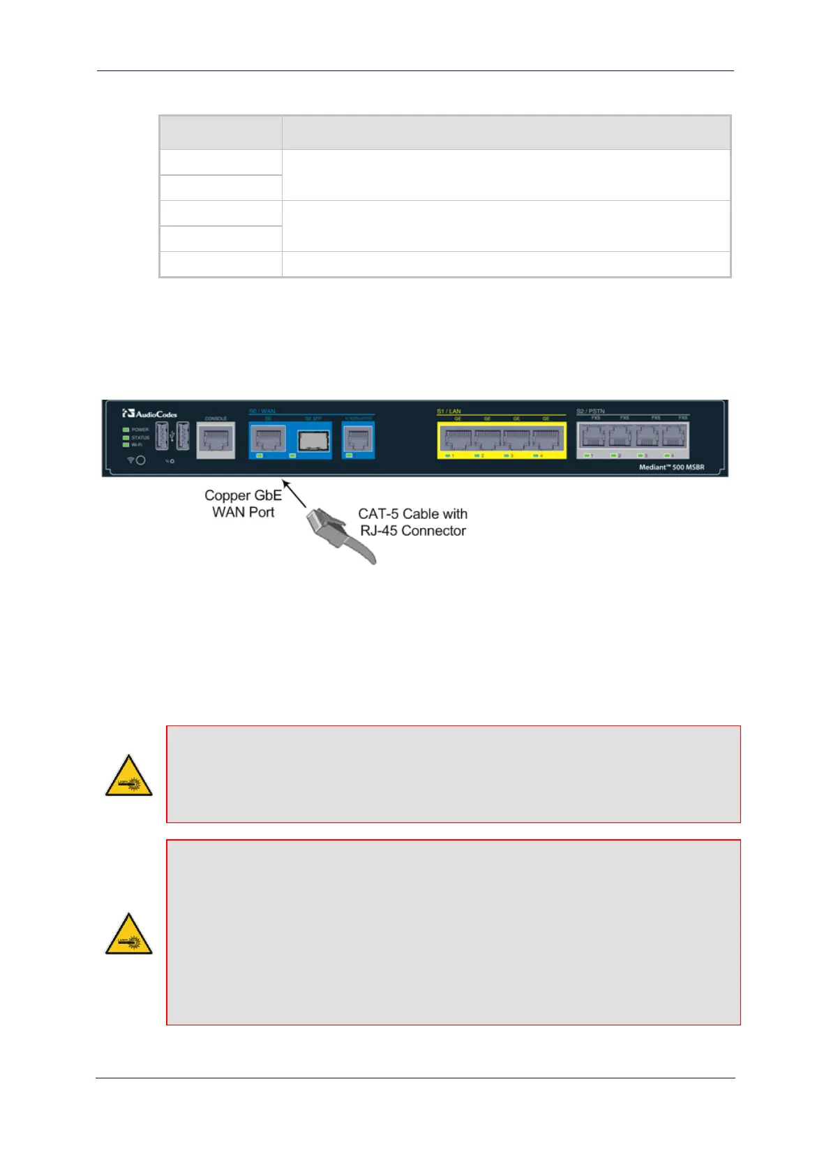
To connect the WAN copper GbE port:
1. Connect one end of a straight-through RJ-45 Ethernet cable to the RJ-45 port labeled
S0 / WAN GE (located on the front panel).
Figure 5-2: Cabling the WAN Copper GbE Port
2. Connect the other end of the cable to the WAN network (e.g., ADSL or Cable modem).
5.2.2 Fiber-Optic Gigabit Ethernet Cabling
The device supports up to two pairs of 1.25 Gbps optical small form-factor pluggable (SFP)
transceiver modules. The SFP module can be used for fiber-optic or copper WAN interface.
Caution Laser
This device contains a Class 1 LED/Laser emitting device, as defined by 21CFR 1040
and IEC825. Do not stare directly into the beam or into fiber optic terminations as this
can damage your eyesight.
Care in Handling Fiber Optic Cabling:
1. Excessive bending of the Fiber Optic Cable can cause distortion and signal losses.
2. Ensure the minimum bending radius recommended by the Fiber Optic Cable supplier.
3. Incoming optic cabling from the network infrastructure can originate from the top of
the rack or from another shelf within the rack. Preserve the minimum-bending ratio
indicated by the cable manufacturer.
4. To ensure full high-availability capabilities, the configuration of the interface to the IP
backbone must include certain redundant features from which two separate fiber optic
cables are entering the device.
 Loading...