Hardware Installation Manual 48 Document #: LTRT-10764
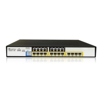
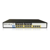
Mediant 500 MSBR
5.6.2 Connecting the FXO Interface
The procedure below describes how to cable the device's FXO interface.
Warning:
• The device does not include primary telecom protection! When the FXO telephone
lines are routed outside the building, additional protection - usually a 350V three-
electrode Gas Discharge Tube (GDT) as described in ITU-T K.44 - must be provided
at the entry point of the telecom wires into the building (usually on the main
distribution frame / MDF), in conjunction with proper grounding. The center pin of the
GDT (MDF grounding bar) must be connected to the equipotential grounding bus bar
of the Telecommunication room.
• To protect against electrical shock and fire, use a minimum 26-AWG wire to the
connect FXO port to the PSTN.
• Ensure that the FXO port is connected to the appropriate, external device; otherwise,
damage to the device may occur.
• The FXO port is considered TNV-3.
Note:
• FXO interface is a customer-ordered item.
• FXO is the interface replacing the analog telephone and connects to a Public
Switched Telephone Network (PSTN) line from the Central Office (CO) or to a Private
Branch Exchange (PBX). The FXO is designed to receive line voltage and ringing
current, supplied from the CO or the PBX (similar to an analog telephone). An FXO
VoIP device interfaces between the CO/PBX line and the Internet.
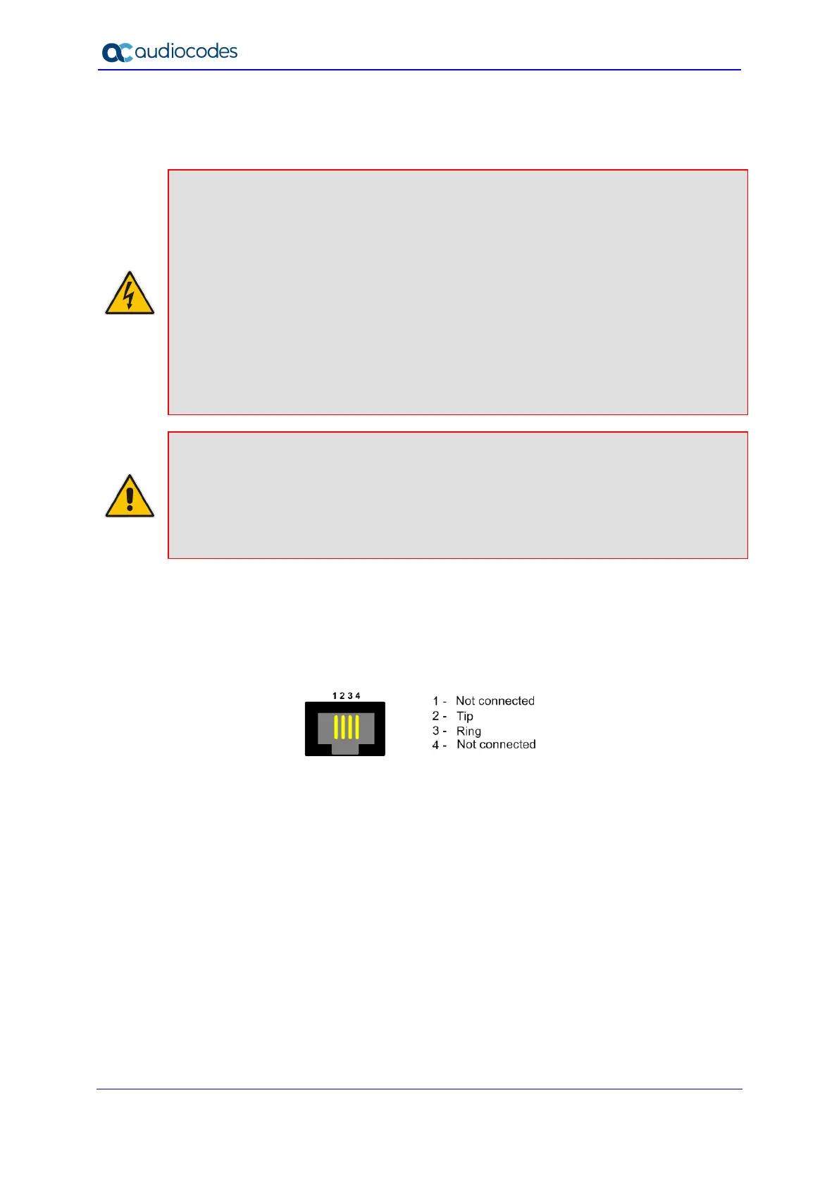
Cable specification:
Cable: 26-AWG min. wire cable
Connector: RJ-11
Connector Pinouts:
Figure 5-16: RJ-11 Connector Pinouts for FXO Interface
 Loading...