4.5. Mounting positions of local controls
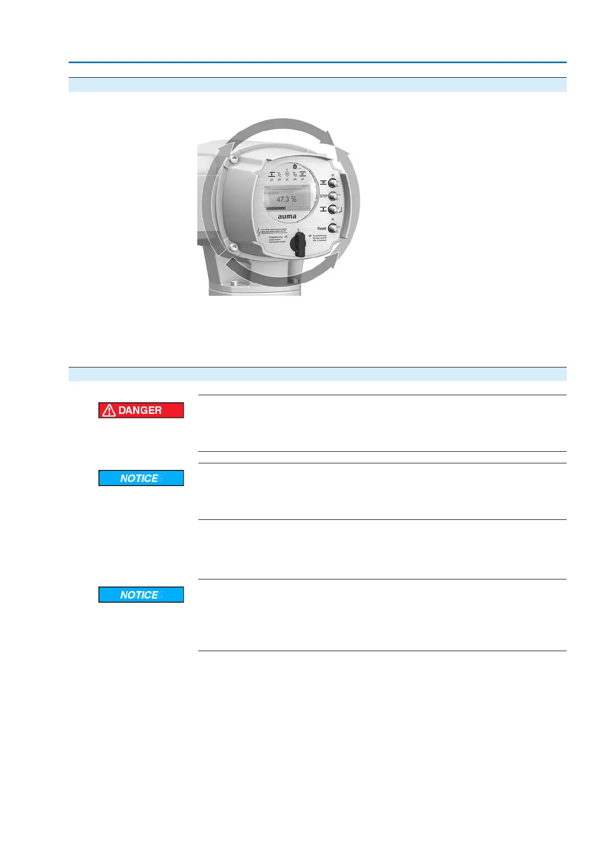
Figure 16: Mounting positions
The mounting position of the local controls is implemented according to the order.
If, after mounting the actuator to the valve or the gearbox on site, the local controls
are in an unfavourable position, the mounting position can be changed at a later
date. Four mounting positions shifted by respectively 90° are possible (by maximum
180° into one direction).
4.5.1. Mounting positions: modify
Hazardous voltage!
Risk of electric shock.
→
Disconnect device from the mains before opening.
Electrostatic discharge ESD!
Risk of damage to electronic components.
→
Earth both operators and devices.
1. Loosen screws and remove the local controls.
2. Check whether O-ring is in good condition, correctly insert O-ring.
3. Turn local controls into new position and re-place.
Cable damage due to twisting or pinching!
Risk of functional failures.
→
Turn local controls by a maximum of 180°.
→
Carefully assemble local controls to avoid pinching the cables.
4. Fasten screws evenly crosswise.
21
SA 07.2 – SA 16.2/SAR 07.2 – SAR 16.2 Control unit: electronic (MWG)
AC 01.2 Non-Intrusive HART Assembly

 Loading...


