5.2.4. HART terminal compartment: open (version with HART connection board)
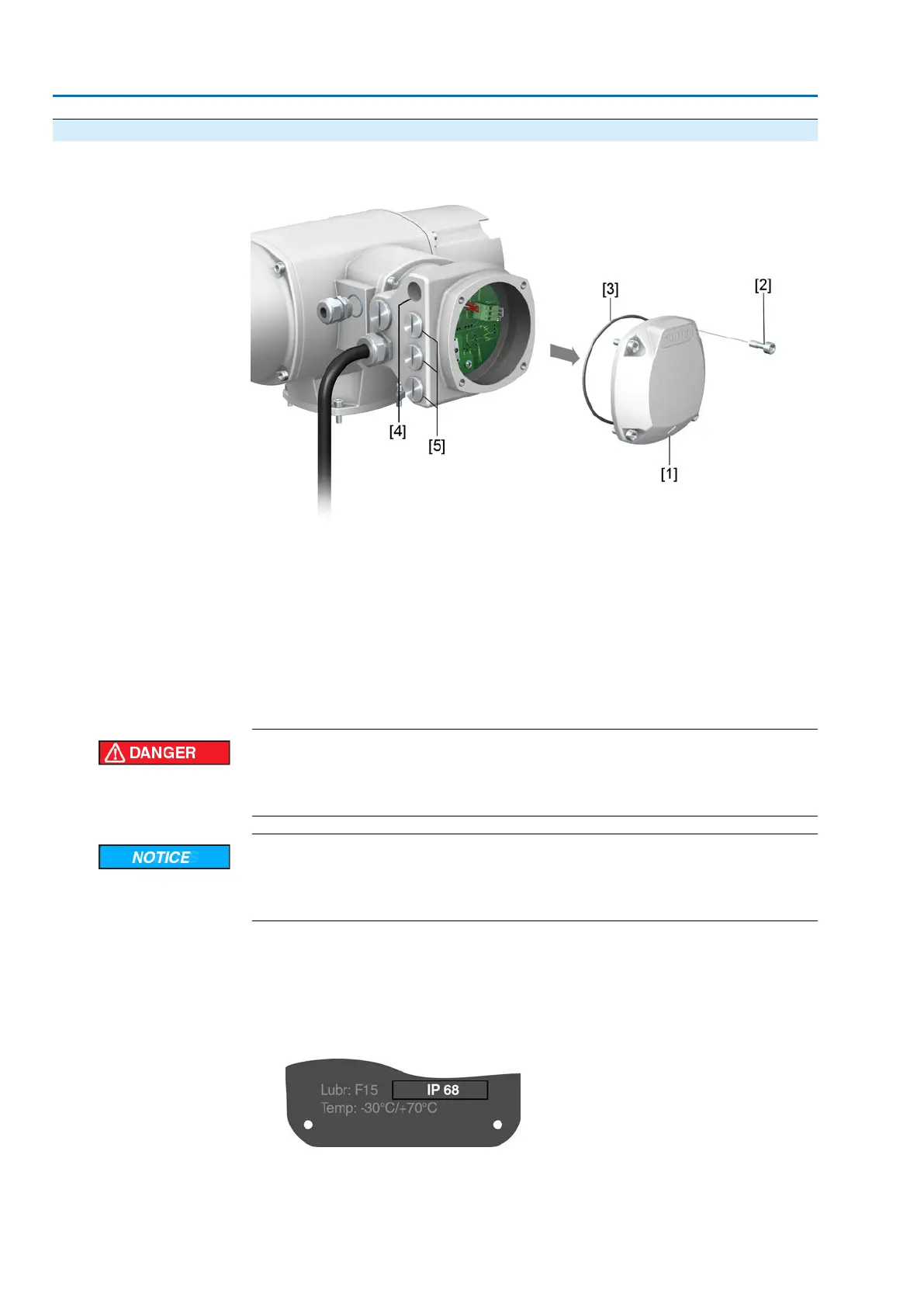
Figure 23: Open cover to HART terminal compartment
[1] Cover (HART terminal compartment)
[2] Screws for cover
[3] O-ring
[4] Cable entries for HART cables
[5] Blanking plug
Only for version with SD electrical connection, with HART connection board.
Hazardous voltage!
Risk of electric shock.
→
Disconnect device from the mains before opening.
Electrostatic discharge ESD!
Risk of damage to electronic components.
→
Earth both operators and devices.
1. Loosen screws [2] and remove cover [1].
2. Insert cable glands suitable for HART cables.
➥
The enclosure protection IP… stated on the name plate is only ensured if suit-
able cable glands are used.
Figure 24: Example: Name plate for enclosure protection IP68
3. Seal unused cable entries with suitable plugs.
30
SA 07.2 – SA 16.2/SAR 07.2 – SAR 16.2 Control unit: electronic (MWG)
Electrical connection AC 01.2 Non-Intrusive HART

 Loading...


