10.2. Mechanical position indicator (self-adjusting)
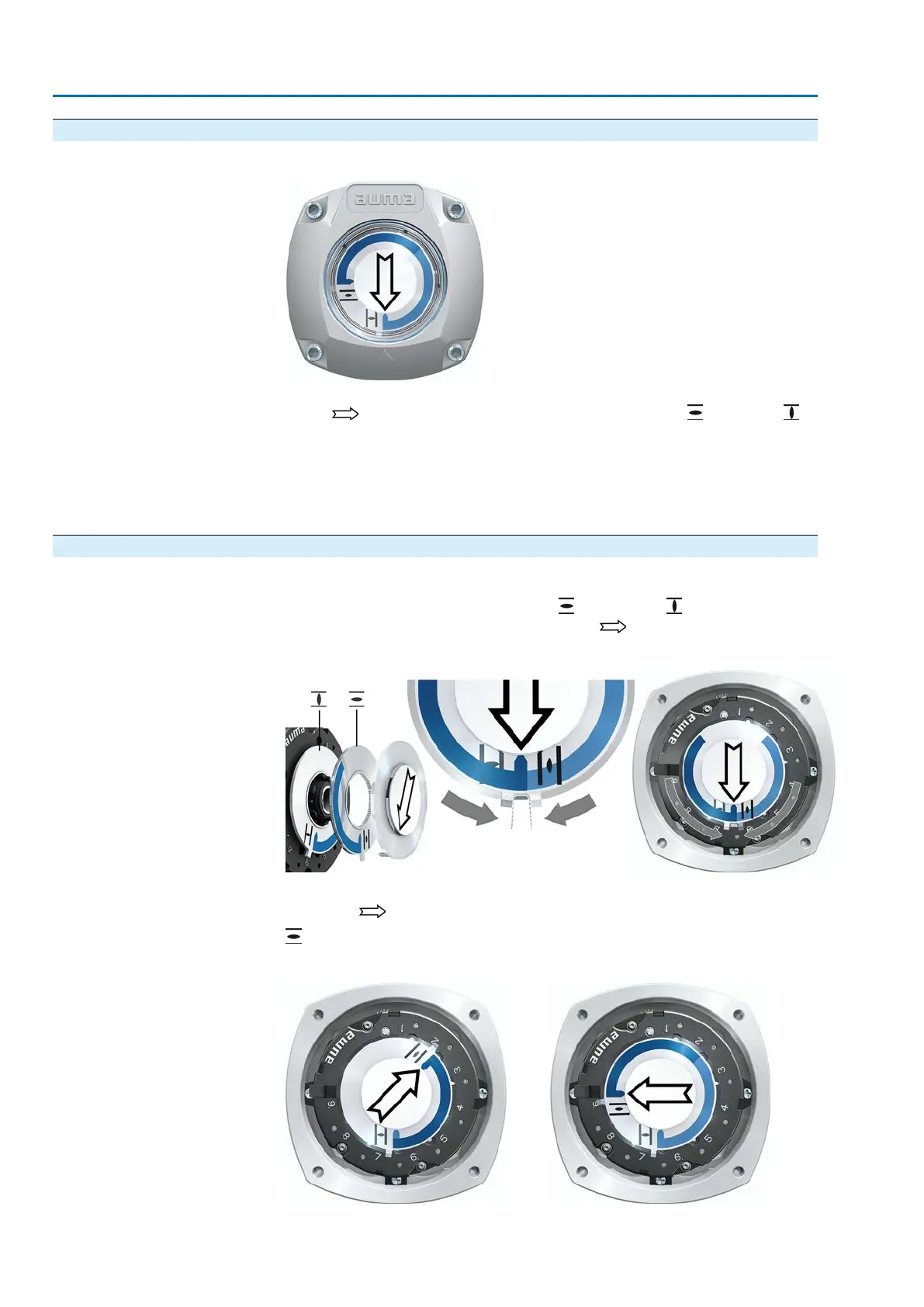
Figure 69: Mechanical position indicator (self-adjusting)
The self-adjusting mechanical position indicator shows the valve position by means
of an arrow . When correctly set, the arrow points to symbol (OPEN) or
(CLOSED) in the end positions.
Information
The position indications is housed in the actuator switch compartment. Opening the
switch compartment for manual setting is only necessary if the gear stage setting
must be modified of if the factory settings of predefined end position CLOSED (or
OPEN) must be adapted when commissioning.
10.2.1. Mechanical position indicator: set
1. Move valve to end position CLOSED.
2.
Push both lower discs with the symbols (OPEN) and (CLOSED) towards
each other. The disc with the arrow is thereby is driven:
Figure 70: Setting position in CLOSED
3. Move actuator to end position OPEN.
➥
The arrow rotates in direction OPEN driving the indicator disc with symbol
(OPEN) until the actuator stops in position OPEN.
Figure 71: Operation in direction OPEN (left) and position OPEN (right)
62
SA 07.2 – SA 16.2/SAR 07.2 – SAR 16.2 Control unit: electronic (MWG)
Commissioning (settings/options in the actuator) AC 01.2 Non-Intrusive HART

 Loading...


