5.2.5. HART cables: connect
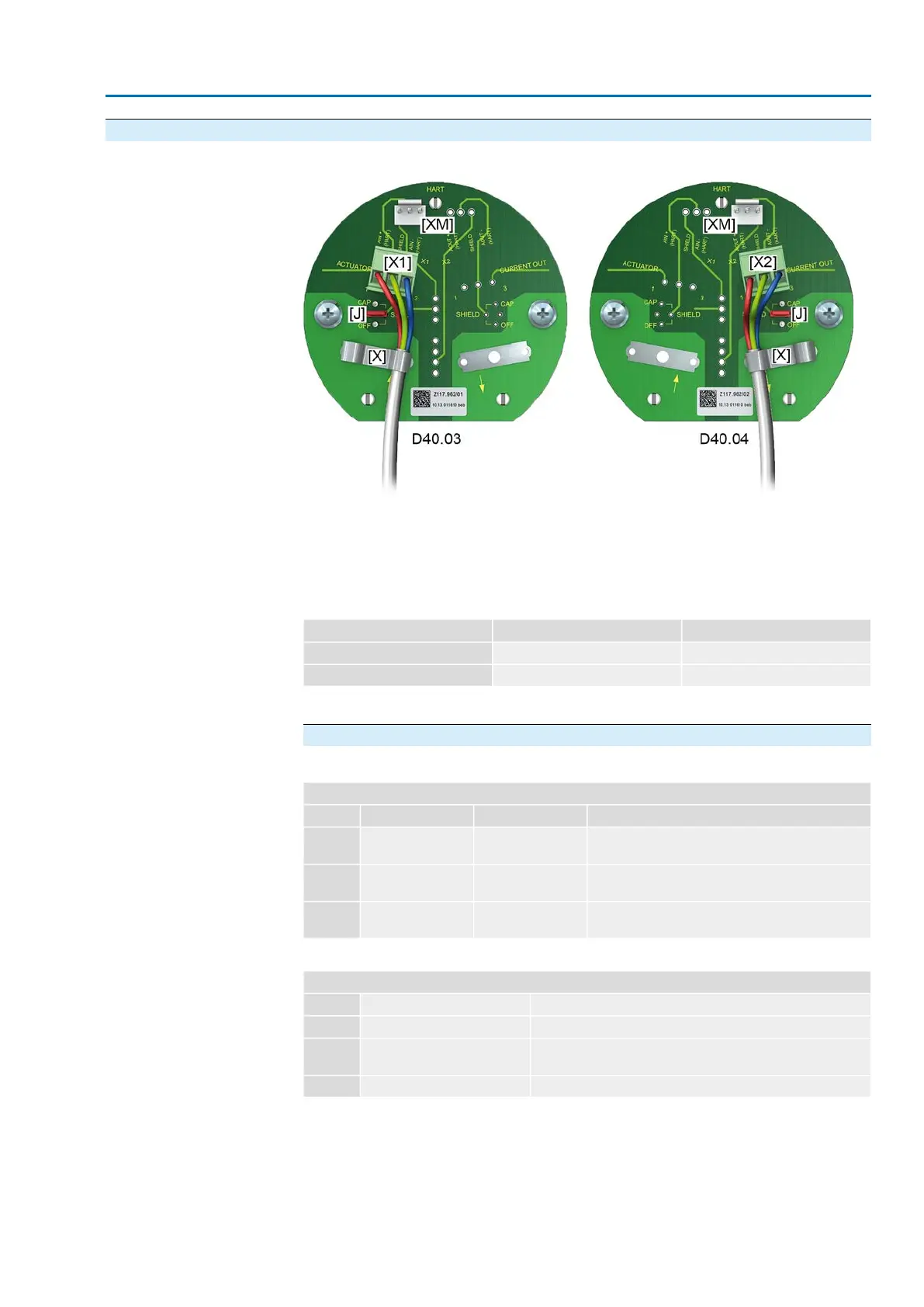
Connection boards Figure 25:Variants of HART connection boards
[X] Shielding clamp
[XM] Connection for HART modem
[X1/2] 4 – 20 mA HART cable
[J] Jumper for shield
Table 14:
AUMA art. no. on label
1)
Device categoryVariant
Z117.962/01ActuatorD40.03
Z117.962/02Current OutputD40.04
Label with article number on connection board1)
Connection assignment for “Actuator” device category
Table 15:
X1, screw-type terminal, 3-pole: analogue connection with HART signal (“Actuator”)
FunctionSignal typeSignalPin
Positive (analogue) input (target value) with HART
signal
Current with HARTAIN+_H1
Wire or shield of infeed cableShield (EMC protec-
tion)
Shield (drain)2
Negative (analogue) input (target value) with HART
signal
Current with HARTAIN-_H3
Table 16:
J: Jumper for shield
FunctionPositionItem
Shield via capacitor (2.2 nF/200 V) to PEJumper from CAP to SHIELD1
Shield directly to PE (default)Jumper from horizontal level
to SHIELD
2
Shield not to PE (not recommended)Jumper from OFF to SHIELD3
31
SA 07.2 – SA 16.2/SAR 07.2 – SAR 16.2 Control unit: electronic (MWG)
AC 01.2 Non-Intrusive HART Electrical connection

 Loading...


