3. Insert cable glands [8] suitable for connecting cables.
➥
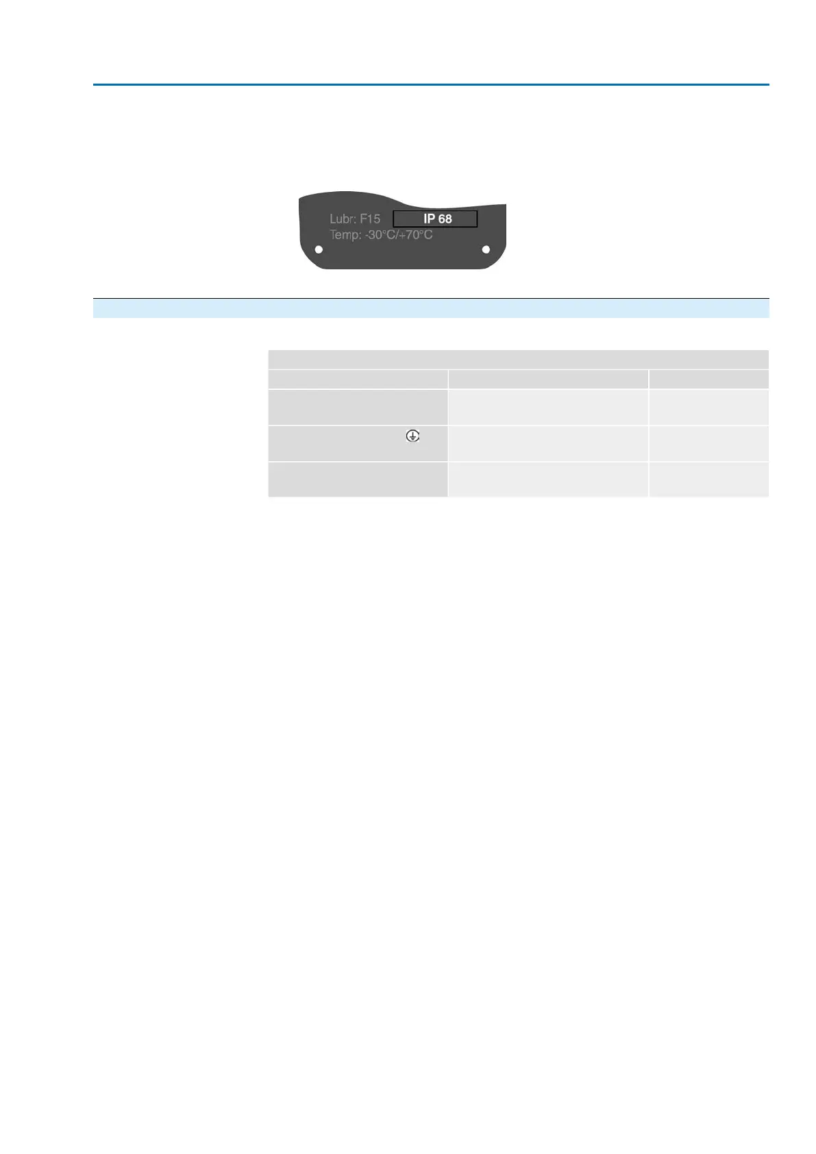
The enclosure protection IP… stated on the name plate is only ensured if suit-
able cable glands are used.
Figure 20: Example: Name plate for enclosure protection IP68
4. Seal unused cable entries [6] with suitable blanking plugs [7].
5.2.2. Cable connection
Table 13:
Terminal cross sections and terminal tightening torques
Tightening torquesTerminal cross sectionsDesignation
1.2 – 1.5 Nm1.0 – 6 mm
2
(flexible)
1.5 – 10 mm
2
(solid)
Power contacts
(U1, V1, W1, U2, V2, W2)
1.2 – 2.2 Nm1.0 – 6 mm
2
(flexible) with ring lugs
1.5 – 10 mm
2
(solid) with loops
Protective earth connection (PE)
0.5 – 0.7 Nm0.25 – 2.5 mm
2
(flexible)
0.34 – 2.5 mm
2
(solid)
Control contacts
(1 to 50)
1. Remove cable sheathing.
2. Insert the wires into the cable glands.
3. Fasten cable glands with the specified torque to ensure required enclosure
protection.
4. Strip wires.
→
Controls approx. 6 mm, motor approx. 10 mm
5. For flexible cables: Use wire end sleeves according to DIN 46228.
6. Connect cables according to order-related wiring diagram.
27
SA 07.2 – SA 16.2/SAR 07.2 – SAR 16.2 Control unit: electronic (MWG)
AC 01.2 Non-Intrusive HART Electrical connection

 Loading...


