5.3. Accessories for electrical connection
5.3.1. Controls mounted on wall bracket
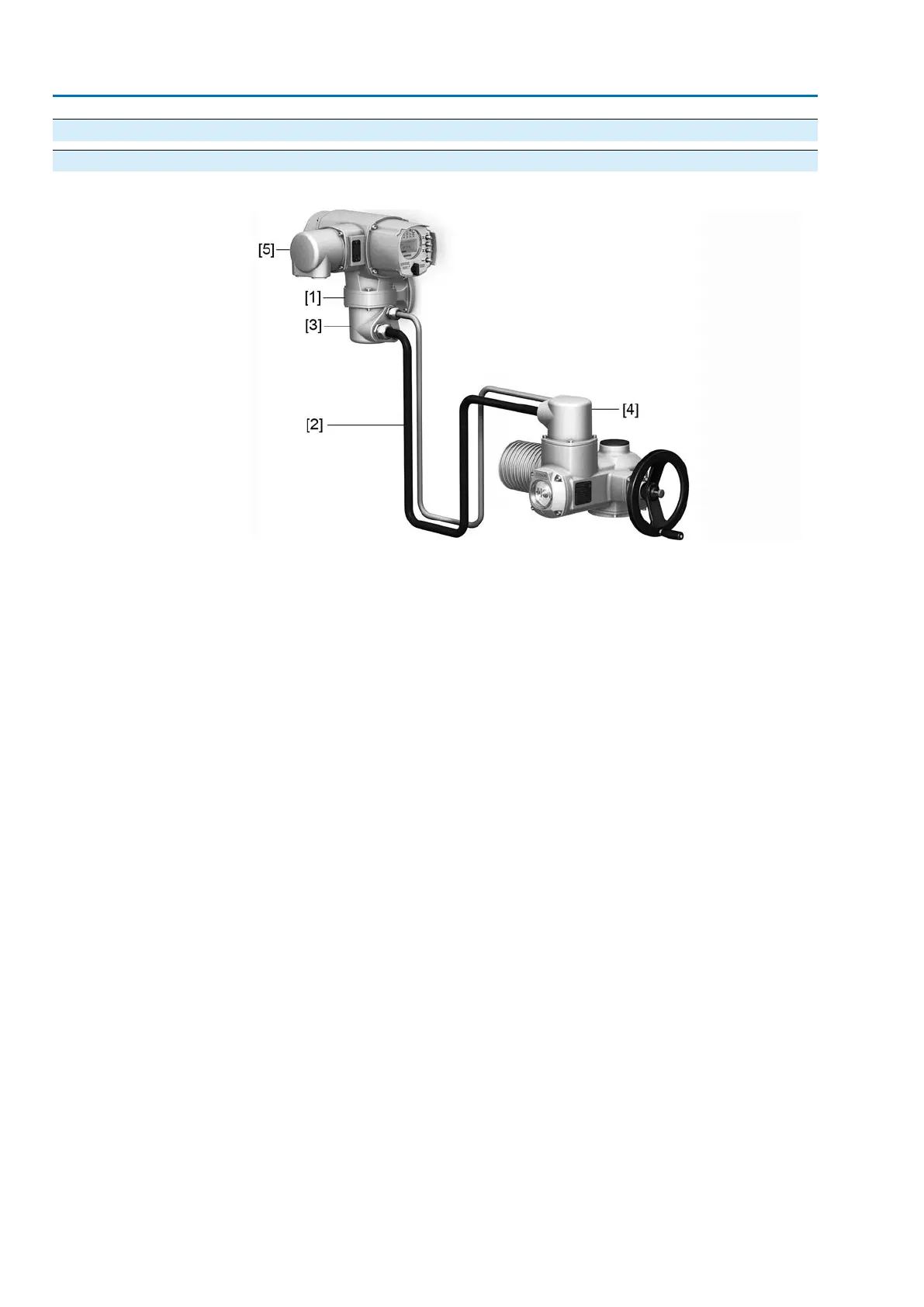
Design Figure 27: Design principle with wall bracket
[1] Wall bracket
[2] Connecting cables
[3] Electrical connection of wall bracket (XM)
[4] Electrical connection of actuator (XA)
[5] Electrical connection of controls (XK) - customer plug
Application
The wall bracket allows separate mounting of controls and actuator.
●
If the actuator cannot be accessed safely.
●
If the actuator is subjected to high temperatures.
●
In case of heavy vibration of the valve.
Observe prior to connec-
tion
●
Permissible length of connecting cables: max. 100 m.
●
We recommend: AUMA cable set LSW20.
●
If the AUMA cable set is not used:
- Use suitable flexible and screened connecting cables.
- Use separate CAN bus cable of 120 Ohm character impedance for MWG
(e.g. UNITRONIC BUS-FD P CAN UL/CSA - 2 x 2 x 0.5 mm², manufacturer:
Lapp).
- Data cable connection: XM2-XA2 = CAN L, XM3-XA3 = CAN H.
- Voltage supply MWG: XM6-XA6 = GND, XM7-XA7 = +24 V DC (refer to
wiring diagram).
- For the electrical connection at wall bracket [3], the terminals are made
as crimp connections.
- Use a suitable four indent crimp tool for crimping.
- Cross sections for flexible wires:
- Control cables: max. 0.75 to 1.5 mm²
- Mains connection: max. 2.5 to 4 mm²
●
When using connecting cables, e.g. of the heater, requiring direct wiring from
the actuator to the XK customer connector (XA-XM-XK, refer to wiring diagram),
these connecting cables must be subject to an insulation test in compliance
with EN 50178. Connecting cables for MWG do not belong to this group. They
may not be subjected to an insulation test.
34
SA 07.2 – SA 16.2/SAR 07.2 – SAR 16.2 Control unit: electronic (MWG)
Electrical connection AC 01.2 Non-Intrusive HART

 Loading...


